
In the Iranian national standard, calibration refers to the comparison of a measuring device with a standard and determining the amount of error in the device relative to the standard, and if necessary, adjusting the calibration in comparison with the relevant standards. In other words, calibration refers to the process of aligning the motion value of an axis with one of the standard units or with a specific value. Common units in industrial devices are usually millimeters, centimeters, meters, inches, feet, degrees, etc., which are available for use based on the need. Therefore, the concept of calibration for the millimeter unit can be expressed as the alignment of the motion value of the desired axis with the millimeter unit. That is, in the case of measuring with measuring tools, the numerical value of the motion of the axis should be consistent with the measured value in millimeters.
In Radonix controller, each axis has the ability to calibrate separately, and even the axes can be calibrated in different units. The variable representing the calibration factor in this controller is the Step variable, which to access it, you need to open the Radonix software and after opening the Setting window, go to the System branch and then the Axis{n} sub-branch ({n} represents the number between 1 to 6, which specifies the axis number.), where the Step variable is located, and each axis has its own specific Step variable. (For more information, please refer to chapter (5) and table (16)
⚠️ The types of calibration methods are:
-
Computational method
-
Measurement method
Computational method
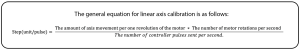
To adjust the axis motion value to the desired unit, we use the calibration coefficient called “Step.” To access this variable, open the software and go to the “System” branch and then the “Axis{n}” sub-branch (where {n} is a number between 1 and 6 representing the axis number). The Step variable is located in each of these sub-branches, and each axis has its own Step variable.
If the unit of axis motion is millimeters, the unit of this variable will be millimeters per pulse. If the unit is centimeters, inches, or any other unit, the Step variable will have the same unit per pulse. It represents the amount of axis motion per pulse sent to the motor driver. Therefore, to calculate this variable, we need to know the relationship between the motor motion value and the input pulse to the driver, as well as the conversion ratios of gearbox, pulleys, and any other motion transmission.
For better understanding of these calculations, consider the following example:
Example 1: Consider a linear axis of a CNC machine with a measurement unit in millimeters, which uses Panasonic A5 motors with a 10/1 gearbox and is connected to a shaft gear with an effective diameter of 66 millimeters via a pinion. Now, calculate the Step value for the given axis.
⚠️ Note that each of these pieces of information plays a fundamental role in these calculations, and by using this information, it is possible to calculate the axis step for calibration. For example, knowing the type of motor driver and its specifications determines the relationship between the input pulse value to the driver and the amount of motor shaft movement.
In Panasonic A5 motors, at a rate of 500,000 pulses per second, the motor reaches a speed of 3,000 RPM. In the first step, we calculate the motor’s rotational speed per second. In this case, the number 3,000 means the number of revolutions per minute. To convert it to seconds, we divide it by 60, which is equal to 50 revolutions per second. Therefore, the equation is written as follows:
Motor speed per second = 3000 (r/m)/60(s)=50 (r/s)
In the second step, we need to calculate the linear displacement for one rotation. In this example, the distance traveled will be equal to the circumference of the circle, which is equal to the diameter of the circle multiplied by pi (3.1415). As mentioned in Example 1, a pinion with a diameter of 66 millimeters and a 10/1
gearbox are used in the mechanics. Therefore, we have:
Linear displacement for one rotation of the motor = (1/10) * 66(mm) * 3.1415 = 20.7339(mm)
The result is the linear displacement for one rotation of the motor.
The final step is to write the final equation and find the unknown variable, which is the Step variable. As we have seen, all calculations are based on 500,000 pulses sent by the controller and the motor speed of 3,000 RPM. Therefore, to calculate the displacement or distance traveled for one pulse, we need to divide the calculated number by 500,000. However, as mentioned, this motor has 50 revolutions per second. So, we need to multiply the result obtained in the second step by 50 to find the total distance traveled per second of motor rotation. Now we will rewrite the general equation.
The step value is calculated from this equation, which means that the motor moves 0.00207339/0 millimeters by taking 1 pulse.
⚠️ Note that the Computational method used in Example 1 is for the calibration of linear axes.
Example 2: Consider the rotary axis of a CNC machine whose measuring unit is in degrees, and Panasonic A5 motors with a 25:1 gearbox connected to a 12-tooth pulley, which is then connected to a 44-tooth pulley via a belt. Now, calculate the step value for the axis in question using computational method 2.
⚠️ Note that one revolution of the shaft is equivalent to 360 degrees.
In Panasonic A5 motors, at a rate of 500,000 pulses per second, the motor reaches a speed of 3000 rpm. Now, in the first step, we calculate the motor rotation speed per second. In this case, the number 3000, which represents the number of motor revolutions per minute, is divided by 60 to convert it to seconds, resulting in the number 50. This means that this motor rotates 50 times per second. Therefore, the equation can be written as follows:
The motor rotation speed per second = 3000(r/m)/60(s)=50(r/s)
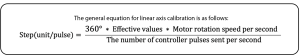
In the final step, we need to multiply the effective values such as gearbox ratio, pulley ratio, and motor rotation speed per second by the number 360. As we have seen, all calculations were based on 500,000 controller pulses and 3000 rpm motor speed. Therefore, to calculate the motion value for 1 pulse, we need to divide the obtained number by 500,000, which will result in the Step value with this simple estimate.
From this equation, the Step value is calculated.
- Note that in both linear and rotary axis calculations, using more significant figures will result in more accurate calculations.
- The pulse divisions in steppers have a direct effect on these calculations, so for the sake of simplicity, the motor rotation value for a specific number of pulses should be calculated first, and then the result should be applied to the above equations.
- In drives where the number of pulses required to reach the maximum motor speed is greater than the number of pulses produced by the controller, increasing the electronic coefficient of the drive by a specific ratio can allow the motor to reach maximum speed. For example, if a drive requires 4 million pulses per second to reach the maximum motor speed and considering the production of 500,000 pulses per second by Radonics, the electronic coefficient of the drive should be increased by a ratio of 8 to reach the maximum motor rotation speed.
Measurement Method
In this calibration method, the basis is measurement with measurement tools and equipment. Therefore, the accuracy of the measuring tool, measurement accuracy, and mechanical errors of the device directly affect the quality of calibration. Although this method is not as precise as computational methods, it is a widely used method due to the lack of information on motors, gearboxes, pulleys, and gear wheels, which are sometimes not available. The basis of this method is measuring the displacement value for a specific number of pulses.
To facilitate, improve accuracy, and speed up calibration using the measurement method, Radonics has provided a free software called CAM-Pro Calibrator, which is automatically installed with the main Radonics software. Based on the physical displacement measurement of the axis and the required number of pulses for this displacement, the software calculates the step value. (Figure 1)
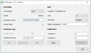
Figure (1)
Since pulse counting in this method is the responsibility of the controller, there is no error in pulse measurement. Therefore, the measurement accuracy in this method is directly related to the physical measurement accuracy. In addition, the greater the distance between the two measured points, the larger the pulse value will be, which means the denominator will increase, and according to the constant error, the overall step value obtained will be more accurate. Therefore, calibrating based on two points will result in more accurate results.
Note that you should never run two Radonix software at the same time because in this case, one of the software will not go online. Therefore, make sure to close the other Radonics software when running the desired software.
Introduction to CAM-Pro Calibrator
As explained in the previous section, the CAM-Pro Calibrator software is installed along with the CAM-Pro software. There are two ways to find the Calibrator software after installation. According to the first method, simply go to the installation location of the software, which is usually in the C drive of Windows by default, then go to the (x86) Program Files folder, open the Radonix folder, and the CAMProCalibrator software is visible in the Radonix CAM-Pro file. According to the second method, simply go to the Start menu and search for Radonix CAM-Pro Calibrator in the Search option (Step 2 in Figure 2).
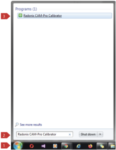
Figure (2)
This program consists of two windows. The first window only runs when multiple interfaces are active on a computer, as shown in Figure (3), and it allows the user to select the desired interface and execute it by clicking the Ok button. If there is only one active interface on the computer, the interface selection window will not appear, and the main window will open directly.
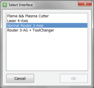
Figure (3)
When opening the CAM-Pro Calibrator software, you will be faced with Figure (4) which includes the following components in order:
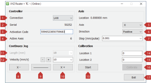
Figure (4)
|
Controller |
|
1 |
Connection |
In ProLan controllers, it should be in LAN mode. In ProUSB controllers, it should be in USB mode. |
|
2 |
Serial |
Displays the controller’s serial number. |
|
3 |
Activation Code |
The 16-digit activation code that activates the axes. |
|
4 |
Active Axes |
Displays the number of axes activated by the activation code. |
|
Axis |
|
5 |
Axis |
Axis is used to select the axis for calibration. |
|
6 |
Direction |
Selecting the appropriate direction of movement to align with standard axes. Negative represents movement towards the negative direction and Positive represents movement towards the positive direction. |
|
7 |
Step |
Step or calibration coefficient is the output of the software that is automatically recorded in the interface after the calibration operation. |
|
Continues Jog |
|
8 |
 |
Manual movement towards the negative axis. |
|
9 |
 |
Used to select the type of manual movement (continuous/discrete). If the sign is it |
|
10 |
 |
Represents manual movement towards the positive axis. |
|
11 |
Length |
Displays the value of incremental movement, which becomes active when selecting incremental movement. |
|
12 |
Velocity |
Used to set the speed of manual movement and the + and – keys next to Velocity are used to increase and decrease the speed of manual movement. |
|
Calibration |
|
13 |
key to start the calibration process. |
|
|
14 |
Location 1 |
Used to determine the initial position for calibration. This position should be measured relative to a fixed point on the measurement axis. |
|
15 |
Location 2 |
Used to determine the end position for calibration. This position should be measured relative to a fixed point on the measurement axis. |
|
16 |
 |
Finish Calibration and Calculate Step or Calibration Coefficient is the key to end the calibration process. |
|
17 |
 |
Exit Program is the key to exit the program. |
For example, to calibrate one of the axes, we must follow the steps below:
First, select the axis to be calibrated from the Axis section. Then, by selecting a low speed and moving the axis, we ensure the direction of the axis movement is correct. If the direction is incorrect, select the appropriate direction from the Direction section. Then, move the axis to one of the two end points of its motion range. Since the starting point is not important in this method, it doesn’t matter which end point is chosen. After positioning the axis in the appropriate place, a point on the axis is measured with a suitable measuring tool relative to a fixed point on the machine and recorded in Location 1. Then, press the Start button. Note that the selection of the unit is entirely optional. Therefore, if the device needs to be calibrated with a specific unit, all measurements must be made in that unit. For example, the device can be calibrated in inches, meters, centimeters, millimeters, or even micrometers.
Move the axis in the opposite direction. If measuring at greater distances is possible and the measuring tool has sufficient accuracy, measurements at greater distances result in more accurate results. After moving the axis to the second point, measure it relative to the fixed point on the measuring machine like the first point, and record it in Location 2. Then, press the Calibrate button. Using these measurements, the calibration step or coefficient is calculated and automatically recorded in the desired interface. Calibration can be performed for any number of axes as needed.
Note that if the activation code is not entered, an error message will be displayed when opening the CAM-Pro Calibrator software