
After installing the software, as described in Chapter 3, and the appropriate interface, you can now use the Radonix software. This section will explain all of the elements used in the software. Figure 6 shows a list of all the installed interfaces. If multiple interfaces are installed on one computer, the user can enable or disable each interface by right-clicking on it and selecting the appropriate option from the menu. The user can also remove the interface from the computer.
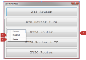
Figure(6)
- Activate the interfaces
- Reactivate the interfaces
- Disable the interface, which is indicated by dimming the caption of the interface
- Completely remove the desired interface from the computer
To open an interface, the user can left-click on any of the software interfaces. Figures 7 and 8 show two examples of interfaces. Each interface displays different icons, depending on its characteristics. For example, Figure 7 includes the X, Y, Z axes, and the ability to change tools, while Figure 8 includes only the X, Y, Z, and A axes, and does not include the ability to change tools. This clearly indicates that Figure 8 is an A-axis controller interface, and the tool-changing feature has been removed in this form. Similarly, other differences can be observed.
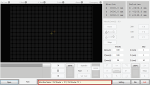
Figure(7)
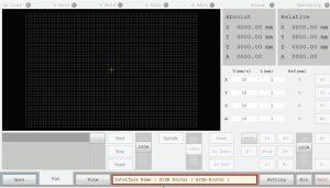
Figure(8)
Introduction of menus and keys on the software page
Understanding the Functionality of Each Button and Component
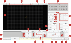
Figure(9)
| Number |
Name Of The Element |
Description |
Shortcut |
|
1 |
Online |
If the controller and software are connected, it is on. If there is no communication between the controller and the software, it will be turned off or displayed in gray color (Figure 9) |
|
|
2 |
X Axis, Y Axis, Z Axis … |
When each axis is active, it will be displayed with a light indicating its activation. If an axis is inactive, it will be turned off and displayed in gray color (as shown in Figure 9). Note that the display of the axes may vary in different interfaces. The interface may display all available axes or a different number depending on the interface’s capabilities. |
|
|
3 |
Alarm |
If there is an error or issue with the connection between the controller and the motors and drives, the indicator will turn on, otherwise, it will remain turned off |
|
|
4 |
Emergency |
In the event of an error in the emergency settings section, the indicator can be adjusted to turn on. Note that the number of emergency device inputs can be defined. |
|
|
5 |
Absolut & Relative |
Absolute: Displays the coordinates of the axes in reference to the home point. Relative: Shows the coordinates of the axes relative to the reference point. Note that the display of the coordinates may vary in different interfaces. The interface may display all available axes or a different number depending on the interface’s capabilities. |
|
|
6 |
Tool Path (Movement path indicator Tool) |
Once a file has been loaded, the movement path will be displayed in this section. Both in simulation mode and during actual operation, you can observe the device’s movements and the sequence of program execution. In the upper left corner, you can see the file’s upload location and the Work Size or Work Length, which displays the sizes in different axes. In the lower right corner, you can view the file from different perspectives and zoom in or out. By holding the right mouse button, you can change the viewing angle of the design. |
|
|
7 |
G-Code display |
Once you have loaded the desired file using the Open button, the Code-G and program lines will be displayed in this section. During program execution, each executed GCode will be highlighted with a different color. |
|
|
8 |
Open |
It is used to load G-Code, dxf, and Autocad files. |
CTRL + SHIFT + ALT + O |
|
9 |
Run |
Tab is program execution. Different interfaces may have more than one tab. |
|
|
10 |
Text box |
In normal mode, this section displays the name of the interface. When a CNC operation is being performed, this section displays the approximate time elapsed and the remaining time of the operation. When an alarm or emergency occurs, this section changes to red. By double-clicking with the left mouse button, the Form Debug window will open. Here, you can view the performance report of the controller and software, including the Radonix software version, interface type, and alarms. By pressing a shortcut key twice, a general performance report of the device will be displayed in Notepad. |
CTRL + SHIFT + ALT +PrtSc |
|
11 |
Setting |
All device parameter settings can be configured in this window. (For more information, refer to section 4.2.2). |
|
|
12 |
Min |
In order to minimize the software window, press the minimize button. |
|
|
13 |
Exit |
To exit the software. |
|
|
14 |
Velocity |
This feature is available in some interfaces and displays the movement speed in ToolPath. If needed, it can be added to interfaces that do not have this feature by default. (For more information, refer to section 4.2.7). |
|
|
15 |
Home |
This feature is available in some interfaces and displays the movement speed in ToolPath. If needed, it can be added to interfaces that do not have this feature by default. (For more information, refer to section 4.2.7). |
Alt + Home |
|
16 |
Go Zero |
By pressing this button, the device will quickly move to the zero point (Home) of the device. The difference between this case and case 15 is that in this case, the device moves quickly to the zero point without the need to slowly approach it to detect the sensors |
|
|
17 |
Go Ref |
In order to move the axes to the zero point of the workpiece or reference point. |
|
|
18 |
Stop |
In order to stop the process of device operation. |
|
|
19 |
X0,Y0,Z0,… |
To determine the reference point, simply click on one of the buttons. The reference point value will be displayed in the box next to the button. Note: The display of available axes may vary depending on the interface and the number of axes. |
Alt+X => X0 Alt+Y =>Y0 Alt+Z =>Z0 |
|
20 |
Velocity text box of axes X(mm/s), Y(mm/s), Z(mm/s),… |
In these text boxes, the movement speed of the axes can be entered, and these values are applied in Continuous mode or if the Jog key is held on the desired axis. In Continuous mode, the value entered in the text box for each axis is represented as a percentage of manual movement speed (in relation to it). The Jog term is multiplied, and by pressing the Jog key, each axis moves at the speed resulting from the product of the Jog term and the value entered in the Velocity text box. For example, if the number entered in the Velocity text box for the Z axis (Figure 11) is 10mm/s, and the Scroll percentage is 100%, the product of these two numbers is 10mm/s. By pressing the Z+ or Z- key, the Z axis moves in the positive or negative direction at a speed of 10mm/s, respectively |
|
21 |
Step text box of axes X(mm), Y(mm), Z(mm),… which are located next to the axes |
In these text boxes, the movement value of the axes is entered, and these values are applied in Incremental mode or when the corresponding Jog key for each axis is pressed. In Incremental mode, the value entered in the text box of each axis is multiplied by the Scroll percentage related to manual movement (also known as Jog), and when the Jog key of each axis is pressed, it moves by the product of the above value. For example, if the value entered in the Step text box for the Z axis (Figure 11) is 50mm and the Scroll percentage is 100%, the product of these two values is 50mm. Thus, each time the Z+ and -Z axis buttons are pressed, it moves 50mm in the positive and negative direction, respectively. |
|
|
22 |
Two-axis movement Simultaneous |
The button for simultaneous movement of two axes is used to move two axes at the same time. It works in the same way as pressing two Jog buttons at the same time, but each axis will move based on its own set parameters and speed. The function is similar to the one described in item 25 of the same table. |
|
|
23 |
Continous and incremental |
This button is a toggle switch, which means that each time you press it, the mode alternates between Continuous and Incremental. In Continuous mode or if you hold the Jog key, the selected axis moves at the set speed. (For more information, see item 20 in the same table) In Incremental mode or by pressing the Jog key each time, the selected axis moves to the specified distance. (For more information, see item 21 in this table). |
|
|
24 |
Scroll |
In fact, the percentage of this scroll is calculated by multiplying the values in the text boxes in manual or jog mode (refer to numbers 20 and 21 in the table for more information). |
|
|
25 |
X+, X-, Y+, Y-… |
To manually move the axes, the Jog axes can be used in two modes: Continuous and Incremental. In Continuous mode, the desired axis moves at the set speed if the Jog key is held. (Refer to number 20 in the same table for more information.) In Incremental mode, the desired axis moves by the set distance each time the Jog key is pressed. (Refer to number 21 in the same table for more information.) |
|
|
26 |
Spindle |
It is to turn the spindle on or off. |
|
|
27 |
Scroll |
It is used to determine the spindle rotation speed. |
|
|
28 |
Play |
It is for the purpose of running the program. |
|
|
29 |
Pause |
To halt the execution of a program, it’s important to note that pressing the Pause button will stop the program on the same G-Code line. The program can be resumed from that line by pressing the Play button again. |
|
|
30 |
Stop |
To stop and reset the program. |
|
31 |
Scroll |
In order to control the execution speed of the program. |
|
|
32 |
(Text box) Tool |
To call a specific tool, the tool number must be entered. When changing tools, if the spindle is holding a tool, it will be placed in its designated location and the tool specified by the number entered in the text box will be taken when the Enter button is pressed. |
|
|
33 |
Set Tool |
It is to set the tool height. |
Table(1)
|
1 |
ConveyorSensorPin |
This is the input of a canoview sensor. When this input is activated, the canoview will turn off. |
||||||||
|
2 |
Axis name ,HomeFastPin |
This is used for a sensor that is located before the Home sensor and moves the machine at a high speed during the Home operation. After activating this input, the machine moves at the speed that was set for the Home operation.
|
||||||||
|
3 |
Axis name, HomePin |
When this input is activated, the home point of the machine is determined.
|
||||||||
|
4 |
InterruptEndSensorPin number, InterruptEndSensorPin |
InterruptEndSensorPin is used for the following two cases: The entire process is executed if a single M code or function command is given. The entire process is executed if two M codes or function commands are given. Note that if InterruptStartSensorPin and InterruptEndSensorPin are not defined for the inputs, the Interrupt process will be executed without the need for the input sensors to be triggered or True. As the Interrupt process is fully related to the input, output, and function links, the complete process performance is described here, and it is sufficient to refer to the corresponding table and define the links based on the pin or function name when defining the process. In addition, in the diagram drawn for better clarity, the sequence of operations and the activation of inputs, outputs, and functions are shown. The links are displayed with abbreviation symbols (Input Link — I), (Output Link — O), and (Function Link — F)
When the Interrupt command (Function Link) is executed, it first waits for the InterruptStartSensorPin input (Input Link) to be triggered, and when the InterruptStartSensorPin input (Input Link) is triggered or True, the command to turn on the InterruptPin output (Output Link) is issued. It then waits for the InterruptEndSensorPin input (Input Link), and if the InterruptEndSensorPin input (Input Link) is triggered or True, the InterruptPin output (Output Link) is turned off, and the process ends. (please refer to appendix 6 – Figure (1))
When the InterruptStart command (function link) is executed, it first waits for the InterruptStartSensorPin input link and when the InterruptStartSensorPin input link is triggered or, in other words, becomes True, the command to turn on the InterruptPin output link and InterruptStartPin output link is issued and the first stage of the process is completed. (please refer to appendix 6 – Figure (2)) When the InterruptEnd command (function link) is executed, first the InterruptPin (output link) and InterruptStartPin (output link) are turned off, and InterruptEndPin (output link) is turned on. Then, it waits for the input of InterruptEndSensorPin (input link), and if InterruptEndSensorPin (input link) is triggered, or in other words, becomes True, InterruptEndPin (output link) is turned off and the final step of the process is completed. (please refer to appendix 6 – Figure (3)) |
||||||||
| 5 |
InterruptStartSensorPin Number, InterruptStartSensorPin |
InterruptStartSensorPin is used for the following two conditions:
Please note that if InterruptStartSensorPin and InterruptEndSensorPin are not defined for the inputs, the Interrupt process will be executed without the need for the input sensor to be triggered or in other words, become True. Since the Interrupt process is completely related to input, output, and function links, the entire process is explained in this section, and when defining the process, the links used are mentioned, and it is sufficient to refer to the relevant table and define the links based on the pin or function name. Additionally, in the diagram that has been drawn for better clarity, the order of operations and the activation of inputs, outputs, and functions are shown. Links are displayed with abbreviations. (Input Link — I), (Output Link — O), and (Function Link — F)
When the Interrupt command (function link) is executed, it first waits for the input of InterruptStartSensorPin (input link), and when the input of InterruptStartSensorPin (input link) is triggered, or in other words, becomes True, the command to turn on the InterruptPin (output link) is issued. Then, it waits for the input of InterruptEndSensorPin (input link), and if InterruptEndSensorPin (input link) is triggered, or becomes True, the InterruptPin (output link) is turned off and the process is completed. (please refer to appendix 6 – Figure (4))
When the Interrupt command (function link) is executed, it first waits for the input of both InterruptStartSensorPin1 and InterruptStartSensorPin2 (input links), and when both inputs are triggered, or in other words, become True, the command to turn on the InterruptPin (output link) is issued. Then, it waits for the input of both InterruptEndSensorPin1 and InterruptEndSensorPin2 (input links), and when both inputs are triggered, or become True, the InterruptPin (output link) is turned off and the process is completed. (please refer to appendix 6 – Figure (5)) When the InterruptEnd command (function link) is executed, first the InterruptPin (output link) and InterruptStartPin (output link) are turned off, and InterruptEndPin (output link) is turned on. Then, it waits for the input of InterruptEndSensorPin (input link), and if InterruptEndSensorPin (input link) is triggered, or in other words, becomes True, InterruptEndPin (output link) is turned off and the final step of the process is completed. (please refer to appendix 6 – Figure (6)) |
||||||||
| 6 |
Axis name, LimitPin |
The input is a limit switch for the axes. When this input is activated, movement is not allowed on the determined axis.
|
||||||||
|
7 |
R-CornerJackSensorPin |
The input is the jack sensor of the table. When this input is activated, it determines whether the jack is on or off. |
||||||||
|
8 |
SimpleCommandSensorPin Number, |
Since the SimpleCommand process is fully related to input, output, and function links, the complete process functionality is explained in this section. To fully clarify the process, the used link is mentioned when defining the process, and it is enough to refer to the related table and define the links based on the pin or function name. In the diagram, for better clarity, the sequence of operations and the activation of inputs, outputs, and functions are shown. The links are displayed with abbreviations. (Input Link — I), (Output Link — O), and (Function Link — F) When the SimpleCommand (function link) command is executed, first the SimpleCommandPin (output link) is turned on, and then it waits for the SimpleCommandSensorPin (input link) to be activated, or in other words, to become True. Once this happens, the SimpleCommandPin is turned off and the process ends. (please refer to appendix 6 – Figure (7)) |
||||||||
|
9 |
SpindleCoverSensorPin |
The input is the spindle cover jack sensor. When this input is activated, the on/off status of the spindle cover is determined. |
||||||||
|
10 |
SurfaceDetectorPin |
The input is the surface detection sensor. When this input is activated, the workpiece level is determined. This input is related to the Z axis of the rotary machine. The SurfaceDetector sensor is usually placed on the workpiece so that after the tool contacts the sensor, the workpiece level is determined. |
|
11 |
SurfaceScanSensorPin |
The input is the surface scan sensor. This input is related to the SurfaceScan function. For more information, please refer to table 4. |
||||||||||
|
12 |
SurfaceScanJackSensorPin |
The input is the scan jack sensor. This input detects the activation of the jack. This input is related to the SurfaceScan function. For more information, please refer to table 4. |
||||||||||
|
13 |
T-CC-S1Pin T-HSD-S1Pin T-TEKNO-S2Pin T-ToolSensorPin |
The input is the tool presence sensor in the spindle collet. When this input is activated, the presence or absence of the tool in the spindle collet is determined.
|
||||||||||
|
14 |
T-CC-S2Pin T-HSD-S2Pin T-TEKNO-S1Pin T-ToolHolderSensorPin |
This input is the spindle clamp sensor which detects the open or closed state of the spindle clamp. When this input is activated, it determines whether the spindle clamp is open or closed.
|
||||||||||
|
15 |
T-CC-S3Pin T-HSD-S3Pin T-TEKNO-S3Pin T-InverterStopPin T-SpindleRotationSensorPin |
he input is a sensor for detecting the rotation of the spindle. When this input is activated, the status of the spindle rotation is determined. In other words, when the spindle is rotating, this input turns on and off once for each revolution of the spindle.
|
||||||||||
|
16 |
Numberm, T-Jack3SensorPin |
The input T-Jack3SensorPin is used during tool change. When this input is activated, the status of the T-Jack3Pin output is displayed (on or off). Using this input increases the safety of the machine and reduces the possibility of errors. If T-Jack3SensorPin is not used, a parameter called Jack3Delay is activated in the Settings window under the ToolChanger branch, where the delay time when turning on or off the T-Jack3Pin output can be entered. This input is related to the T-Jack3Pin output. Please refer to Table 3 for more information.
|
||||||||||
|
17 |
Number, T-JackSensorPin |
The input is a jack sensor used during tool changing. When this input is activated, the status of the T-JackPin output is displayed as on or off. Using this input increases the safety of the device and reduces the likelihood of errors. If this input is not used, a parameter called JackDelay is activated in the ToolChanger section under the Settings window. It is possible to enter the delay time for turning on or off the T-JackPin output. This input is related to the T-JackPin output. Please refer to Table 3 for more information.
|
||||||||||
|
18 |
T-SpindleHomePin |
The input is used to determine the Home position of the spindle tool. In some spindle machines that have tool changing capability, the tool must be placed in a specific position or the Home position before continuing the tool change process. This input is used to ensure that the tool is first placed in the correct position before continuing the tool change process. Typically, the T-SpindleHomePin sensor is connected to the spindle structure. This input is related to the T-SpindleLockPin output. Please refer to table 3 for more information. |
||||||||||
|
19 |
T-ToolHeightSensorPin |
When this input is executed, the height of the tool is determined. This input is related to the output called T-ToolHeightPin. Please refer to table 3 for more information on this output. This input is related to the T-SetToolHeight function. Please refer to table 4 for more information on this function. |
Table(2)
|
Name of the Element |
Descriptions |
|||||||||||||||||||||||||||||||||||
|
1 |
AlarmPin |
If the ClearAlarm function is executed, this output will be turned on for 0.5 seconds. |
||||||||||||||||||||||||||||||||||
|
2 |
Axis name, AlarmStatusPin |
In case of an alarm occurring in the designated axis, the output is turned on.
|
||||||||||||||||||||||||||||||||||
|
3 |
Axis name, AlarmStatusPin |
If the direction of movement for the designated axis is positive, this output turns on, and if the movement is in the negative direction, the output turns off.
|
||||||||||||||||||||||||||||||||||
|
4 |
Number, Axis name, AlarmStatusPin |
X4 is a hardware designed by the company Radonics, which has the capability of switching a single axis to four axes and includes 4 input channels. By connecting the digital outputs of a controller to the X4 inputs, it enables the control of up to 4 motors completely separately on a single axis. For example, on the Z-axis, it is possible to connect up to 4 motors and turn them on or off separately. (please refer to appendix 6 – Figure (8)) Note that these four outputs can also be used in combination. In other words, any combination of them can be turned on or off simultaneously. To do this, simply turn on the output connected to the desired X4 input. Note that this output is related to the AxisSwitch function. Please refer to table 4, row 2 for more information.
|
||||||||||||||||||||||||||||||||||
|
5 |
BinaryOutPortPin, Number |
By executing the command, the output is turned on in binary format. For example, it can be used to control the spindle speed in binary format. Suppose an inverter has four inputs for speed control, and it is sufficient to define four outputs with the links BinaryOutPortPin, 0, BinaryOutPortPin, 1, BinaryOutPortPin, 2, and BinaryOutPortPin, 3, and connect them to the inputs of the inverter in order.
|
||||||||||||||||||||||||||||||||||
|
6 |
BrakePin |
After the controller goes online and the motors are powered, executing the BrakePin command will turn on the output connected to the brake relay, releasing the brake 1 second after the motors are powered on. |
||||||||||||||||||||||||||||||||||
|
7 |
ControlStatusPin, Number |
Various states of the controller and software can be viewed
|
||||||||||||||||||||||||||||||||||
|
8 |
ConveyorPin |
By executing the command to turn on or off the conveyor motor, this output will turn on or off. When the conveyor sensor (ConveyorSensorPin) in the inputs is activated, this output will be automatically turned off. There is also a function related to turning on the Conveyor, please refer to row 10 in table 4 for more information. |
||||||||||||||||||||||||||||||||||
|
9 |
CoolantPin |
By executing the command to turn on or off the cooling system of the machine, this output will turn on or off. Usually, this output can be controlled through the M code (M8). For the operation of this pin, there is a function called Coolant. For more information, please refer to row 11 in table 4. |
|
10 |
Axis name, EnabledStatusPin |
When the designated axis is enabled, this output is turned on.
|
||||
|
11 |
Axis name, ErrorStatusPin |
When the specified axis has an alarm or limit, this output turns on.
|
||||
|
12 |
InterruptEndPin Number, InterruptEndPin |
InterruptEndPin is only used in a situation where the entire process is executed in case of two M codes or two functions. Note that if InterruptStartSensorPin and InterruptEndSensorPin are not defined for inputs, the Interrupt process is executed without the need for the input sensor to be triggered or an expression to be True. Considering that the Interrupt process is completely related to the input, output, and function links, the complete operation of the process is explained in this section, and in order to be fully clear, the used pin is mentioned when defining the process, and it is enough to define the links according to the pin name or function and refer to the corresponding table. In addition, the order of operations and the activation of inputs, outputs, and functions are shown in a diagram for greater clarity. The links are displayed with abbreviations: (Input Link — I), (Output Link — O), (Function Link — F).
In a case where the entire process is executed in response to two M codes or two functions: When the InterruptStart command (function link) is executed, it first waits for the InterruptStartSensorPin input link to be triggered or in other words become True, and when that happens, it issues the command to turn on the InterruptPin (output link) and InterruptStartPin (output link), and the first stage of the process is completed. (please refer to appendix 6 – Figure (9)) When the InterruptEnd (function link) command is executed, first the InterruptPin (output link) and InterruptStartPin (output link) are turned off, and then the InterruptEndPin (output link) is turned on and waits for the InterruptEndSensorPin (input link) to be triggered or in other words become true. When the InterruptEndSensorPin (input link) is triggered, the InterruptEndPin (output link) is turned off and the final stage of the process ends. (please refer to appendix 6 – Figure (10)) |
||||
|
13 |
InterruptPin Number, InterruptPin |
InterruptPin is used for the following two cases: When the entire process is executed in case of a single M code or a single function. When the entire process is executed in case of two M codes or two functions. Note that if InterruptStartSensorPin and InterruptEndSensorPin are not defined for the inputs, the Interrupt process will be executed without the need for the input sensor to be triggered or True. As the Interrupt process in the input, output, and function links are fully related to each other, the entire process is explained in detail in this section. To make it clear, the link used is mentioned when defining the process, and it is sufficient to refer to the corresponding table and define the links according to the pin name or function. Also, in the diagram that is drawn for better clarity, the order of operations and the activation of inputs, outputs, and functions are shown. The links are displayed with abbreviation symbols. (I: input link), (O: output link), (F: function link)
In the case where the entire process is executed upon a command of an M-code or a function, when the Interrupt command (function link) is executed, it first waits for the input of InterruptStartSensorPin (input link), and when the input of InterruptStartSensorPin (input link) is triggered or True, the command to turn on InterruptPin (output link) is issued, and then it waits for the input of InterruptEndSensorPin (input link), and if InterruptEndSensorPin (input link) is triggered or True, InterruptPin (output link) is turned off and the process ends. (please refer to appendix 6 – Figure (11)) In the case where the entire process is executed upon a command of two M-codes or two functions, when the InterruptStart command (function link) is executed, it first waits for the input of InterruptStartSensorPin (input link), and when the input of InterruptStartSensorPin (input link) is triggered or True, the commands to turn on InterruptPin (output link) and InterruptStartPin (output link) are issued, and the first stage of the process ends. (please refer to appendix 6 – Figure (12)) When the InterruptEnd command (function link) is executed, first the InterruptPin (output link) and InterruptStartPin (output link) are turned off, and the InterruptEndPin (output link) is turned on, then it waits for the input of InterruptEndSensorPin (input link), and if InterruptEndSensorPin (input link) is triggered or True, InterruptEndPin (output link) is turned off and the final stage of the process ends. (please refer to appendix 6 – Figure (13)) |
||||
|
14 |
InterruptStratPin Number, InterruptStratPin |
InterruptStartPin is only used in the case where the entire process is executed upon a command of two M-codes or two functions. Note that if InterruptStartSensorPin and InterruptEndSensorPin are not defined as inputs, the Interrupt process will be executed without the need for the input sensor to be triggered or True. Since the Interrupt process in the input, output, and function links are all interrelated, the complete operation of the process is explained in this section. To make it completely clear, the links used are mentioned when defining the process, and it is sufficient to refer to the corresponding table and define the links based on the pin or function name. In the diagram, drawn for more clarity, the sequence of operations and the activation of inputs, outputs, and functions are shown. Links are represented by abbreviations (input link — I), (output link — O), (function link — F)
In the case where the entire process is executed by the command of two M codes or two functions: When the InterruptStart command (function link) is executed, it first waits for the InterruptStartSensorPin input (input link) to be triggered, or in other words, to become True. Once the InterruptStartSensorPin input is triggered, the command to turn on the InterruptPin output (output link) and InterruptStartPin output (output link) is issued and the first stage of the process is completed. (please refer to appendix 6 – Figure (14)) In the next stage, when the InterruptEnd command (function link) is executed, the InterruptPin output (output link) and InterruptStartPin output (output link) are first turned off, and the InterruptEndPin output (output link) is turned on. Then, it waits for the InterruptEndSensorPin input (input link) to be triggered, and if the InterruptEndSensorPin input is triggered or, in other words, becomes True, the InterruptEndPin output (output link) is turned off, and the final stage of the process is completed. (please refer to appendix 6 – Figure (15)) |
||||
|
15 |
Number, JogModePin |
To display the Jog mode, if the entered argument is proportional to the Jog mode, the output will be turned on. For example, if the argument is zero and the Jog mode is Continuous, the output will be turned on.
|
||||
|
16 |
Axis name, JogStatusPin |
If the specified axis is in Jog mode or being jogged, the output will be turned on.
|
||||
|
17 |
LaserPointerPin |
In a device equipped with a pointer laser, this output is used. When this output is turned on, the pointer laser is turned on as well. |
||||
|
18 |
Axis name, LimitNStatusPin |
When the specified axis is at the negative limit, this output is turned on.
|
||||
|
19 |
Axis name, LimitPStatusPin |
When the specified axis is at the positive limit, this output is turned on.
|
|
20 |
Axis name, LimitStatusPin |
When the limit is taken from the specified axis, this output becomes clear. |
||
|
21 |
LubricationPumpPin |
This output is activated when the oiling command is executed. |
||
|
22 |
R-CornerJackPin |
This output is activated when the spindle orientation command is executed. |
||
|
23 |
ReadyPin |
When the controller goes online, this output is turned on. |
||
|
24 |
Axis name, ReadyStatusPin |
When the specified axis is in Ready state and there is no active Alarm condition, this output is turned on.
|
||
|
25 |
Axis name, RunStatusPin |
When the specified axis is in Run state, this output is turned on.
|
||
|
26 |
SelectPin, Number |
It is possible to define any number of outputs as needed. When one output is turned on, the other defined outputs are turned off. In fact, only one of the outputs can be turned on in that unit at a time. This output is associated with a function called “Select”, which allows the user to define Toggle keys as desired (up to a maximum of 32) and by pressing this key, the corresponding output defined by the SelectPin is turned on, and if another output has been defined by the SelectPin, it will be automatically turned off. For example, by defining three Toggle keys with links Select,1, Select,2, and Select,3 and connecting them to three outputs with links SelectPin,1, SelectPin,2, and SelectPin,3, when the Select,1 key is pressed, output 1 is turned on, and outputs 2 and 3 are turned off automatically.
|
||
|
27 |
SimpleCommandPin, Number |
Due to the complete relationship between the SimpleCommand process in the input, output, and function links, the operation of the entire process is fully explained in this section. To be clear, the link used is mentioned when defining the process, and it is sufficient to refer to the corresponding table and define the links based on the name of the pin or function. In the diagram, which shows the order of operations and the activation of inputs, outputs, and functions more clearly, the links are displayed with abbreviations. ((Input link — I), (Output link — O), (Function link — F)) When the SimpleCommand command (Function link) is executed, first the SimpleCommandPin (Output link) is turned on, and then it waits for the SimpleCommandSensorPin input (Input link) to be triggered, and if the SimpleCommandSensorPin input is triggered, or in other words, becomes True, the SimpleCommandPin (Output link) is turned off, and the process is completed. (please refer to appendix 6 – Figure (16)) |
||
|
28 |
SimpleDelayPin |
As the SimpleDelayPin command is fully related to the SimpleDelay function, the operation of the entire process is explained in this section. To be clear, the link used is mentioned when defining the process, and it is sufficient to refer to the corresponding table and define the links based on the name of the pin or function. When the SimpleDelay command (Function link) is executed, based on the argument entered in the SimpleDelay function, the SimpleDelayPin output (Output link) is turned on or off, and then a delay is created for the amount of time set in the SimpleDelay parameter in the General branch in the Setting window. |
||
|
29 |
SpindleCCWPin |
The Spindle direction of movement is determined using it. This output is similar to the output called SpindleCWPin, with the difference that its direction of movement is opposite to the direction of rotation of SpindleCWPin. In fact, their functions are opposite to each other. |
|
30 |
SpindleCWPin |
The Spindle direction of movement is determined using it. This output is similar to the output called SpindleCCWPin, with the difference that its direction of movement is opposite to the direction of rotation of SpindleCCWPin. In fact, their functions are opposite to each other. |
|
31 |
SpindleCoolerPin |
The output is turned on or off with the turning on or off of the Spindle fan |
|
32 |
SpindleCoverPin |
The output is turned on or off with the opening or closing of the Spindle cover. |
|
33 |
SurfaceScanJackPin |
When the Surface Scan command is issued, the SurfaceScanJackPin output is turned on, and when the surface scanning process is finished, the SurfaceScanJackPin output is turned off. This output is associated with an input called SurfaceScanJackSensorPin. For more information, please refer to Table 2. |
|
34 |
T-Jack3Pin |
Machines use a jack as part of the tool changing process, such that when the tool change command is issued and the machine is in the desired position, the jack becomes active and moves the tool holder forward, thereby changing the tool. This is used, for example, to change rotary tools installed on the Z and Y axes. This output is associated with an input called T-Jack3SensorPin. For more information, please refer to Table 2. |
|
35 |
T-JackPin |
When the tool change command is issued, the T-JackPin output is turned on, and when the tool change process is complete, the T-JackPin output is turned off. For example, the tools may be held in a collet, and a jack may be needed to move the collet forward to access the spindle. Depending on the mechanical structure of the machine, the jack can be used to move the tool holders, tool covers, or the entire tool changing system forward and backward by turning the jack on or off. This output is associated with an input called T-JackSensorPin. For more information, please refer to Table 2. |
|
36 |
T-NormalToolChangingPin |
When the tool change command is issued, the T-NormalToolChangingPin output is turned on, and when the tool change process is complete, the T-NormalToolChangingPin output is turned off. This output is similar to the output called T-ToolChangingPin, but is used for some tool changes that use clamps. |
|
37 |
T-SpindleLockPin |
The Spindle Lock output is used in some tool-changing spindles where the type of collet used is important for positioning and rotating the tool. In this case, the spindles must first position the tool in a special position or the tool home point. To do this, a sensor called T-SpindleHomePin is defined, which positions the tool in a special position, and then, if the T-SpindleLockPin output is defined and the tool is in the desired position, the output is turned on. This is done to lock the tool in that special position, so that it does not move from that position. Usually, the T-SpindleHomePin sensor is connected to the spindle structure. This output is associated with an input called T-SpindleHomePin. For more information, please refer to Table 2. |
|
38 |
T-ToolChangingPin |
When the tool change command is executed, this output is turned on, and when the tool change process is complete, it is turned off. This output is similar to the T-NormalToolChangingPin output, but can be used for both normal and Head Changer tools. |
|
39 |
T-ToolCleanerPin |
This output is used to activate an electric valve connected to the tool cleaner. During a tool change, before the machine removes the selected tool, this output is turned on to clean the tool, and then the machine proceeds to remove the tool. |
|
40 |
T-ToolHeightPin |
This output is turned on when the T-SetToolHeight process starts and turned off when the T-SetToolHeight process is complete. For example, a tool height sensor can be connected to a jack, and this output can be used to move the sensor in or out of a compartment by turning the jack on or off, in order to prevent the sensor from getting dirty or damaged. This output is associated with an input called T-ToolHeightSensorPin. For more information, please refer to Table 2. This output is related to a function called T-SetToolHeight. For more information, please refer to Table 4. |
||||
|
41 |
T-ToolHolderPin |
When the command to hold or release a tool inside the spindle is executed, this output turns on or off. This output is similar to the output called T-ToolLockPin, with the difference that T-ToolHolderPin releases the tool when turned on, while T-ToolLockPin holds the tool in place and prevents it from being released when turned on. In fact, their functions are opposite to each other. This output is related to the T-ToolHolder function. Please refer to Table 4 for more information. |
||||
|
42 |
T-ToolLockPin |
When the command to hold or release the tool inside the spindle is executed, this output is turned on or off. This output is similar to the output called T-ToolHolderPin, but the T-ToolLockPin keeps the tool inside the spindle when it is turned on, while the T-ToolHolderPin releases the tool when it is turned on. In fact, their functions are opposite to each other. |
||||
|
43 |
T-ToolPin, Tool number T-ToolPin, Tool number, Tool number |
If the tool number matches the value entered as an argument, the defined output with T-ToolPin link will be turned on.
|
||||
|
44 |
VaccumPin |
By executing the command to turn on or off the Vaccum, this output is turned on or off. |
||||
|
45 |
Zone |
When the axes are within the desired range, the output is turned on or off. And it is possible to define any number of outputs. |
table(3)
|
Name of the Element |
Descriptions |
|||||||||
|
1 |
AJog, Axis name |
Absolute Jog is an abbreviation for manually moving to a specific coordinate, also known as jogging. In this function, we only specify the desired axis for manual movement. The AJog link is related to the parameter link, and all you need to do is enter the coordinates in the Value field, and by executing this function, the desired axis will be moved to the specified coordinates.
|
||||||||
|
2 |
AxisSwitch, Axis name, Number |
A hardware called X4 is embedded, which includes four input channels. By connecting the outputs to the inputs of X4, up to four motors in a single axis can be controlled separately. For example, on the Z-axis, up to four motors can be connected and turned on or off separately. With the motors turned on, the corresponding output pulse for the Z-axis is transmitted to those motors. (please refer to appendix 6 – Figure (17)) Please note that these four outputs are also used in combination. In fact, each one can be turned on or off simultaneously, and it is sufficient to turn on or off the output connected to the desired X4 input. By executing this function, the outputs connected to the X4 hardware inputs can be turned on or off. Please note that this function is related to the AxisSwitchPin output link (Table 3).
|
||||||||
|
3 |
BlockNumber |
By executing this function, the program is moved to the line number specified in the G-Code. To enter the line number, a Value field can be used. |
||||||||
|
4 |
Brake |
By executing this function, the motor brake is manually turned on or off.
|
||||||||
|
5 |
CJog, Axis name |
To define Jog or Continuous manual motion mode.
|
||||||||
|
6 |
Capture |
Reserve |
||||||||
|
7 |
ClearAlarm |
By executing this function, the motor alarm can be cleared. Note that to use this function, the motor in question must have hardware capability to clear the alarm. |
||||||||
|
8 |
ClearPoints |
By executing this function, all points saved by the SavePoint function can be cleared. The SavePoint function is described in row 68 of the same table. Please refer to it for more information, |
||||||||
|
9 |
ClearToolPath |
By executing this function, you can delete the file that has been displayed in ToolPath, |
|
10 |
Conveyor, Axis name |
By executing this function, you can turn the conveyor on or off. If the conveyor sensor (ConveyorSensorPin) defined in the input links is available, the conveyor output can be automatically turned off.
|
||||||||||
|
11 |
Coolant, Number |
This function turns on or off the output related to the cooling system of the machine. In a router machine, the air power switch is connected to it, and with the CoolantPin output, the power switch can be turned on or off. Additionally, the output can be controlled through the M code (M8).
|
||||||||||
|
12 |
Displace, Number |
By executing this function, without running the program, the axes are moved to a specific point on the machine according to the entered argument.
|
||||||||||
|
13 |
DisplaceReference, Axis Name |
By defining this function, the RealTimeReferenceDisplace parameter is added in the General section of the Setting window, and if the user enables or, in other words, sets it to True, they can use this function during program execution, and if it is False, they must first stop program execution and then use the DisplaceReference function. During program execution, by running this function, the Reference point of the workpiece can be moved. In other words, it is used to correct errors that the user needs to correct during program execution. For example, during program execution, the user realizes that the design has an error at a specific point and can correct the error by changing the Reference at that moment.
|
||||||||||
|
14 |
EditGCode |
By running this function, a window will open that allows you to edit G-code. |
||||||||||
|
15 |
Emergency, Text |
The text that the user wants to be displayed in case of an Emergency can be added.
|
||||||||||
|
16 |
Exit |
This function is used to close the program. Before exiting the program, it checks the Dictionary section to see if any text has been written for “Exit”. If there is any text, it displays that message before exiting the program. If no text is written, and if the program is not running or the machine is not homing or moving manually, it will exit the program without any message. |
||||||||||
|
17 |
ExportSetting |
By executing this function, the program settings can be exported. |
||||||||||
|
18 |
Feed, Number |
By executing this function, the program execution speed can be changed. The Scroll function uses the Feed function to change the program execution speed, and the user can set the speed value using the Value parameter. Additionally, by providing an argument, the number of steps to increase or decrease the program execution speed can be specified. In other words, by running this function, the program speed is increased or decreased by multiplying the value of the argument with the number of steps determined.
|
||||||||||
|
19 |
FindCode |
By running this function, you can search for a specific code inside the G-Code program. Essentially, this function opens a page where you can type in the desired code to search for. For example, if the user searches for the code “M30,” it will display in which line of the G-Code program the code “M30” exists. |
|
20 |
Flip, Axis Name |
By executing this function, the symmetry of the design is created.
|
||||||||
|
21 |
Floor, Number |
By executing this function, you can set a coordinate on the Z-axis that the tip of the tool should not move lower than. Essentially, the Z-axis is moved to the specified point for setting the Floor coordinate, and then with this function, that point is saved. This setting will also be applied to the G-Code by opening the desired G-Code. If the Reference or G-Code is lower than the Floor level, the values will be cut by the amount specified for the Floor setting. Note that any changes to the Floor setting will require reopening the file for the command to be applied to the G-Code.
|
||||||||
|
22 |
Frame, Number |
This function draws a rectangle around the design, and the axes move according to the coordinates of the rectangle. It is used to check if the cutting design is included in the workpiece. The user needs to open the G-Code before applying this function. By executing this function, the parameter FrameOverReference is added to the General branch, and any value entered in the FrameOverReference parameter moves from the Reference point to the rectangle. For example, if the FrameOverReference parameter is 10 millimeters, it moves 10 millimeters above the Reference point on the path.
|
||||||||
|
23 |
GenerateG-Code |
By executing this function, G-Code is generated from the points saved in SavePoint. The SavePoint function is explained in row 68 of this table, please refer to that section for more information. |
||||||||
|
24 |
HandwheelA, Axis Name |
HandwheelA is an abbreviation for Handwheel Axis, which is used to determine the axes on which the handwheel is active. It is possible to create a toggle key for each axis, and by pressing each key, the handwheel of that axis is selected.
|
||||||||
|
25 |
HandwheelX, Number |
By executing this function, the Planck’s constant can be determined. Normally, the Planck’s constant is set to 1, 10, 100, or 1000, but it can be set to any value.
|
||||||||
|
26 |
Hold, Text |
By executing this function, all axis movements (Jog and Run) are halted. In fact, the axes are released from any movement until the cause of Hold (which can be an input sensor or a key defined with the Hold function) is resolved. After the removal of the cause, the axes are re-enabled again.
|
||||||||
|
27 |
HoldJog, Text |
By executing this function, manual movement or Jogging of the axes is disabled. In fact, the axes are released from any Jog movement until the cause of HoldJog (which can be an input sensor or a key defined with the HoldJog function) is resolved. After the removal of the cause, the axes are re-enabled again.
|
||||||||
|
28 |
HoldPreRun, Text |
By executing this function, the axis movements during program execution are halted. In fact, the axes are released from any movement during program execution until the cause of HoldPreRun (which can be an input sensor or a key defined with the HoldPreRun function) is resolved. After the removal of the cause, the axes are re-enabled again. In this case, if the program is running and the cause of the HoldPreRun command is activated, the program will continue to run until the end of execution and allows the work to be completed, but it does not allow the program to execute the next Run command until the cause of HoldPreRun is resolved. In this case, if the program is running and the cause of the HoldPreRun command is activated, and the Stop button is pressed, it does not allow the program to execute the Run command.
|
||||||||
|
29 |
HoldRun, Text |
By executing this function, the axis movements during program execution are halted. In fact, the axes are released from any movement during program execution until the cause of HoldRun (which can be an input sensor or a key defined with the HoldRun function) is resolved. After the removal of the cause, the axes are re-enabled again.
|
|
30 |
Home Home, Number Home, Axis name |
|
||||||||||
|
31 |
InPort, Number |
By executing this function, the inputs can be turned on or off.
|
||||||||||
|
32 |
Interrupt Interrupt, Number |
Considering that the Interrupt process in input, output, and function links are fully related, the operation of the entire process is fully explained in this section, and for clarity, the used link is mentioned when defining the process, and the user needs to refer to the corresponding table based on the pin name or function and define the links. Additionally, in the diagram drawn for better clarity, the order of input, output, and function operations and activations are shown. Links are displayed with abbreviations. ((Input Link — I), (Output Link — O), (Function Link — F))
When the entire process is executed in response to an M code or a function command: When the Interrupt command (function link) is executed, the program waits for the InterruptStartSensorPin input link to be triggered or become True. Once this happens, it issues a command to turn on the InterruptPin output link. It then waits for the InterruptEndSensorPin input link to be triggered or become True. If this happens, it turns off the InterruptPin output link, and the process ends. (please refer to appendix 6 – Figure (18)) |
||||||||||
|
33 |
InterruptEnd InterruptEnd, Number |
InterruptEnd is only used in the case where the entire process is executed upon the command of two M codes or two functions. Note that if InterruptStartSensorPin and InterruptEndSensorPin are not defined for inputs, the Interrupt process will be executed without the need for input sensors to be triggered or become True. Since the Interrupt process is fully related to the input, output, and function links, the complete operation of the process is explained in this section, and in order to be completely clear, the links used are mentioned when defining the process, and the user can refer to the relevant table based on the name of the pin or function and define the links. Also, in the diagram drawn for clarity, the order of operations and the activation of inputs, outputs, and functions are shown. The links are displayed with abbreviated symbols. ((Input Link I), (Output Link O), (Function Link F))
When the entire process is executed in case of two M codes or two functions command: When the InterruptStart (function link) command is executed, it waits for the InterruptStartSensorPin input link to be triggered or in other words become True. Then, the command to turn on the InterruptPin and InterruptStartPin output links is issued, and the first stage of the process is completed. (please refer to appendix 6 – Figure (19)) When the InterruptEnd (F) command is executed in the case that the entire process is executed by two M codes or two functions, it first waits for the InterruptEndSensorPin (I) input and when the InterruptEndSensorPin input is triggered or in other words set to True, it turns off the InterruptPin and InterruptStartPin (O) outputs and turns on the InterruptEndPin output. Then it waits for the InterruptEndSensorPin input again and when it is triggered or set to True, it turns off the InterruptEndPin output, and the final stage of the process ends. (please refer to appendix 6 – Figure (20)) |
||||||||||
|
34 |
InterruptManual |
By executing this function, you can enable or disable the Interrupt process. If InterruptManual is True, the Interrupt process will be completely disabled, and if it is False, it will be enabled. |
||||||||||
|
35 |
InterruptStart InterruptStart, Number |
InterruptStart is only used in cases where the entire Interrupt process is executed by two M codes or two functions commands. Please note that if InterruptStartSensorPin and InterruptEndSensorPin are not defined as inputs, the Interrupt process will be executed without requiring the input sensor to be triggered or True. Since the Interrupt process is fully interconnected in input, output, and function links, the entire process operation is fully explained in this section. To make it clear, the used link is mentioned when defining the process, and the user can define the links according to the pin name or function. Also, in the diagram that has been drawn for more clarity, the order of operations and the activation of inputs, outputs, and functions have been illustrated. Links are displayed with abbreviations. ((Input Link — I), (Output Link — O), (Function Link — F))
In the case where the entire process is executed in the event of two M codes or two functions being commanded: When the InterruptStart command (function link) is executed, it waits for the InterruptStartSensorPin input link, and when the InterruptStartSensorPin input link is triggered or becomes True, the command to turn on the InterruptPin (output link) and InterruptStartPin (output link) is issued, and the first stage of the process is completed. (please refer to appendix 6 – Figure (21)) When the InterruptEnd command (function link) is executed in the case where the entire process is executed based on two M codes or two functions, first the InterruptPin (output link) and InterruptStartPin (output link) are turned off, and the InterruptEndPin (output link) is turned on. Then, it waits for the InterruptEndSensorPin (input link) and if the InterruptEndSensorPin is triggered or becomes true, it turns off the InterruptEndPin (output link) and the final step of the process is completed. (please refer to appendix 6 – Figure (22)) |
||||||||||
|
36 |
Jog, Axis name |
To execute this function, a manual movement command, also known as Jog, is given.
|
||||||||||
|
37 |
JogFeed, Number |
By executing this function, the speed of manual or jog movement is changed.
|
||||||||||
|
38 |
JogMod, Number |
By running this function, you can set the state of Jog or manual movement command.
|
||||||||||
|
39 |
LaserPointer, Number |
By executing this function, the laser pointer can be turned on or off. There is also a folder called “LaserPointer” in the “References” branch, which is used to apply an offset in the X and Y directions for the laser pointer.
|
|
40 |
LimitJog, Axis name |
By executing this function, it is possible to limit the manual movement of the axes.
|
||||||||||
|
41 |
Lubricate |
This function performs a one-time oiling process. |
||||||||||
|
42 |
Minimize |
This function minimizes or makes the software window smaller. |
||||||||||
|
43 |
MoveToEnd, Axis name |
By executing this function, the axis specified as the argument is moved to the end point of the axis.
|
||||||||||
|
44 |
MoveToZero, Axis name |
By running this function, the axis specified as an argument will be moved to the zero point.
|
||||||||||
|
45 |
NextFile, Number |
In the GCode folder, there is a parameter called MultiFileEnable which, when enabled, adds a feature to the software that allows opening multiple files simultaneously. In this case, a list of selected files is available to the user, and the user can move between them. This function is used to move between files and control the execution of each selected file. The name of the function is not provided in the given text.
|
||||||||||
|
46 |
OpenFile OpenFile, File address |
Executing this function opens the file selection window.
|
||||||||||
|
47 |
OpenMachine, Interface name |
This function allows direct access to the interface specified in the argument without the need to exit the current interface and enter another interface. It is used for devices that have various uses and require different interfaces.
|
||||||||||
|
48 |
OpenRecentFile |
By running this function, the last file opened by the user will be reopened. This function can be used even if a portion of the program has been executed and the user has exited the software. The program will reopen from the exact point where the user exited and can continue the program execution. In the General branch, there is a parameter called OpenRecentFile which, if enabled, will automatically execute this function when the program is opened. |
||||||||||
|
49 |
OpenReport |
Upon running this function, the following window opens, providing the user with information about the project. (please refer to appendix 6 – Figure (23))
|
|
50 |
OpenSetting |
By executing this function, the Setting window opens. |
||||||
|
51 |
OpenSimpleCAM |
Reserve |
||||||
|
52 |
OpenTab, Number |
By running this function, the desired tab can be opened. The number of the tab can be found in the registry section of the Radonix software in the system.
|
||||||
|
53 |
OutPort, Number, Number, … OutPort, Number |
By executing this function, the outputs can be turned on or off. It can be controlled manually using the Momenty key or the Toggle key. If the Momenty key is used, the operation is performed as soon as the function is executed and is stopped when the key is released. If the Toggle key is used, the operation is performed once by pressing the key and to stop the execution, the key must be pressed again.
|
||||||
|
54 |
R-CornerJack, Number |
By executing this function, you can turn on or off the spindle.
|
||||||
|
55 |
ReferenceABCentre ReferenceABCentre, Axis name |
By running this function, the average of two points A and B selected by the SavePoint function is calculated and the resulting number is considered as a reference. The SavePoint function is explained in row 69 of the same table, please refer to it for more information.
|
||||||
|
56 |
RemoteFunctionRun |
Reserve |
||||||
|
57 |
RemoteFunctionSelect |
Reserve |
||||||
|
58 |
ReplaceLocation |
By executing this function, the ToolPath is moved to a selected point. For example, if a program is running and the user pauses it to move the axes to a new position, this function can be used to move the ToolPath to the new position. Then, by pressing the Run button, the program continues from the new point. |
||||||
|
59 |
Rerun Rerun, Axis name |
By executing this function, the program will be repeated without creating any stop. Additionally, this function can be applied to an M-code and that M-code can be added to the G-code program, in which case the program will be repeated.
|
|
60 |
Reset Reset, Axis name |
By executing this function, the tool is moved to the beginning of GCode and ToolPath is reset. Additionally, this function can be applied to an M code and added to the GCode program.
|
||||||||||
|
61 |
RestoreInterface |
By executing this function, the program’s Backup is used. For example, if the program’s settings have been mistakenly changed by the user, this function can be used to revert to the program’s Backup. Ctrl+Alt+Shift+R is actually the shortcut for this function. By pressing Ctrl+Alt+Shift+F12, the interface settings can be reset. In other words, unused parameters are removed, the interface structure is updated, and the program’s Backup is used for the settings. |
||||||||||
|
62 |
Rotate |
By executing this function, a window will open and by entering the angle in the Angle (Degree) box and pressing the Ok button, the design can be rotated around the Z-axis. (please refer to appendix 6 – Figure (24)) |
||||||||||
|
63 |
Run, Number |
By running this function, the program is executed.
|
||||||||||
|
64 |
RunApplication, File address RunApplication, File address, B |
By executing this function, the desired application is opened. In fact, the function takes the address of an application file and opens the application from that address.
|
||||||||||
|
65 |
RunTimer, Timer name |
This function is used to call the desired timer. By executing the function, the timer starts to function according to the settings made in the Timer section of the Seeting window. In the Timer section of the Seeting window, users can create any number of timers they need.
|
||||||||||
|
66 |
SJog, Axis name SJog, Axis name, Axis name SJog, Number |
By executing the SJog function, it is possible to move the desired axis in the specified direction incrementally.
|
||||||||||
|
67 |
SaveFile |
By executing this function, the GCode file is opened and saved. For example, the user may have resized the file, changed the file’s angle, or made other changes that require the modified file to be saved, and this function can be used for that purpose. |
||||||||||
|
68 |
SavePoint |
|
||||||||||
|
69 |
SaveSecureFile |
This function is used in cases where the user wants to use a specific file and for some reasons doesn’t want that file to be executable on a system other than their own. For example, by executing this function, it asks the user for the device serial number and encodes the file with that serial number. The encoded file can only be executed on the device with the same serial number. The extension of the encoded file is RCSF. (please refer to appendix 6 – Figure (25)) |
|
70 |
Scale |
By running this function, a window is opened and you can scale or resize the X, Y, and Z axes. By default, the scale of the axes is 100 percent. A negative value on any axis reverses that axis. (please refer to appendix 6 – Figure (26)) |
||
|
71 |
Select, Number |
By executing this function, multiple outputs are defined in a way that each output, when activated, will deactivate the others automatically. This function is related to a link named “SelectPin” which allows the user to define up to 32 Toggle keys, and by activating each key, the corresponding output defined by SelectPin will be turned on, while if another output has been defined by SelectPin, it will be turned off automatically. For example, we define three Toggle keys with links Select,1, Select,2, and Select,3, and then we define three outputs with links SelectPin,1, SelectPin,2, and SelectPin,3. By activating the key Select,1, the output 1 will turn on and outputs 2 and 3 will turn off automatically in order. This function is only applicable to the Toggle key.
|
||
|
72 |
SelectFeed, Number |
Based on the given text, this function is used to detect the type of input selector connected to the input, whether it is binary or decimal, because different input selectors can have different types. If SelectBinaryFeed is set to True in the General tab, the connected selector is considered as binary, and if it’s set to False, the connected selector is considered as decimal. The function adds a parameter called SelectBinaryFeed to the General tab.
|
||
|
73 |
SelectReference, Refereance number |
|
||
|
74 |
SetG54 |
By executing this function, the current coordinates with their axis will be considered as G54 reference. |
||
|
75 |
SetG55 |
By executing this function, the current coordinates with their axis will be considered as G55 reference. |
||
|
76 |
SetG56 |
By executing this function, the current coordinates with their axis will be considered as G56 reference. |
||
|
77 |
SetG57 |
By executing this function, the current coordinates with their axis will be considered as G57 reference. |
||
|
78 |
SetG58 |
By executing this function, the current coordinates with their axis will be considered as G58 reference. |
||
|
79 |
SetG59 |
By executing this function, the current coordinates with their axis will be considered as G59 reference. |
|
80 |
SetOutPort, Number |
By executing this function, it is possible to turn on or off outputs. This function is usually not used on a toggle key.
|
||||||||
|
81 |
SetPark |
Executing this function sets the current coordinates of the axes as the Park coordinates. |
||||||||
|
82 |
SetReference SetReference, Axis name SetReference, Axis name, Axis name … |
By executing this function, the current coordinates with the axes in it are considered as the reference coordinates. If the machine has a Pointer and the Pointer is active, the user first specifies the point that they want the machine to be referenced to using the Pointer, and then the Pointer automatically calculates the offset and calculates the actual reference coordinates, considering them as the reference coordinates. For more information, please refer to rows 6 and 40 of this table.
|
||||||||
|
83 |
ShapeScanner |
By executing this function, the machine starts to scan the workpiece to display an approximate shape of the workpiece. |
||||||||
|
84 |
SimpleCommand, Number |
In SimpleCommand process, since the input links, output links, and function are closely related to each other, the complete process is explained in this section, and in order to be completely clear, the used link is mentioned during the process definition. Users can refer to the corresponding table and define the links based on the pin name or function. Also, in the diagram, which is drawn for more clarity, the order of operations and the activation of inputs, outputs, and functions are shown. The links are represented by the following abbreviations: ((Input Link — I), (Output Link — O), (Function Link — F))
When the SimpleCommand command (function link) is executed, it first turns on the SimpleCommandPin (output link) and then waits for the SimpleCommandSensorPin (input link) input and if the SimpleCommandSensorPin (input link) is triggered or in other words becomes True, it turns off the SimpleCommandPin (output link) and the process ends. (please refer to appendix 6 – Figure (27)) |
||||||||
|
85 |
SimpleDelay, Number |
When the SimpleDelay command (function link) is executed, depending on the entered argument, it turns on or off the SimpleDelayPin output link and then waits for the amount of time set in the SimpleDelay parameter in the Setting window under the General branch.
|
||||||||
|
86 |
Simulation, Number |
This function restarts the program and allows switching the program mode to simulation mode or exiting simulation mode and returning to normal mode. In simulation mode, the program can be executed without the need for a controller or hardware.
|
||||||||
|
87 |
Spindle, Number |
This function can be used to turn on or off a spindle.
|
||||||||
|
88 |
SpindleCooler, Number |
By running this function, the spindle cooling output can be turned on or off.
|
||||||||
|
89 |
SpindleCover, Number |
By running this function, the spindle cover output can be turned on or off.
|
|
90 |
SpindleSpeed, Number |
By executing this function, the spindle speed can be changed. In fact, the Scroll function that changes the spindle speed uses this function, and by using the Value link, the speed value of the program can be determined. This function can also be defined for a button or an input, and depending on the argument entered, the Step factor can be specified. In the Router branch in the Setting window, there are several parameters that are related to this function (explained in detail in the Router branch description), including SpindleMaxSpeed, SpindleMinSpeed, SpindleSpeedStep, and so on.
|
||||
|
91 |
Stop |
By executing this function, the operation of the device is paused during program execution, jog movement, and homing operation. |
||||
|
92 |
StopHome, Axis name StopHome, Axis name, Axis name |
By executing this function, the operation of the axis or axes specified as an argument is paused during Homing operation.
|
||||
|
93 |
StopJog, Axis name StopJog, Axis name, Axis name … |
By executing this function, the movement of the axis or axes specified as arguments is paused during manual jogging.
|
||||
|
94 |
StopRun |
This function pauses the machine operation during program execution. |
||||
|
95 |
StopRunReset |
By executing this function, the machine is paused during program execution and is also returned to the first line of the program (G-Code). In case of running the program again, it will start the program from the beginning. |
||||
|
96 |
StopTimer, Timer name |
By running this function, the timer is disabled. In the Timer branch of the Setting window, the user can create as many timers as needed.
|
||||
|
97 |
SurfaceDetector, Axis name |
This function sets the workpiece level. There is also an input link named SurfaceDetectorPin in the table of input links, which is used to define the input or sensor named SurfaceDetector, and by executing the SurfaceDetector function, the workpiece level is determined.
|
||||
|
98 |
SurfaceScan |
By running this function, the workpiece surface is scanned, and if there are any protrusions or depressions on the workpiece surface, the function applies changes to the G-Code to level the surface. |
||||
|
99 |
T-SelectTool T-ToolNo |
This function is used to display the current tool number of the machine, and also allows the tool to be changed by changing the tool number. |
|
100 |
T-SetToolHeight |
By executing this function, the tool height of the machine can be set. This function is linked to an output called T-ToolHeightPin. Please refer to table 3 for more information. This function is also linked to an input called T-ToolHeightSensorPin and an input called T-SetToolHeight. Please refer to table 2 for more information. |
||||||
|
101 |
T-ToolHolder, Number |
This function is used to open and close the tool holder inside the spindle. By defining the T-ToolHolder function and turning it on, the T-ToolHolderPin output, which is connected to the electrical valve inside the spindle, is turned on and holds or releases the tool inside the spindle according to the specified argument. This function is related to the T-ToolHolderPin output. Please refer to table 3 for more information. Note that if the spindle is on or the machine is running during the program, this function is disabled for safety reasons.
|
||||||
|
102 |
ToggleOutPort, Number ToggleOutPort, Number, Number, … |
This function turns on the output pin or pins specified as arguments if they are off, and turns them off if they are on.
|
||||||
|
103 |
TransformXY |
By executing this function, a window opens that allows scaling and rotating a design around the Z axis. The scaling factor for each axis can be set using the X, Y, and Z fields, and the design can be rotated around the Z axis by entering an angle in degrees in the Angle field. In the default state, the scale of each axis is set to 100%. Negative values can be used for the scale to create symmetry. (please refer to appendix 6 – Figure (28)) |
||||||
|
104 |
Vaccum, Number |
By executing this function, you can turn on or off a vacuum output.
|
||||||
|
105 |
Zoom, Number |
By executing this function, the Zoom operation is applied to the file displayed in ToolPath.
|
|
Name of the Element |
Descriptions |
|||
|
1 |
AnalogFeed |
By running AnalogFeed, it is possible to change the execution speed of the program or feed in an analog manner. |
||
|
2 |
AnalogJog, Axis name |
By running AnalogJog, the manual or jog motion command is given in an analog manner via the execution of the JoyStick command, and the speed of the manual motion can also be controlled. The AnalogJog command is effective in JoySticks because some of the JoyStick buttons are analog. Also, by changing the pressure applied to the button, the analog level in the JoyStick button is decreased or increased, and with the change in the analog level, the Jog speed is also changed.
|
||
|
3 |
AnalogJogFeed |
It is used as a coefficient for AnalogJog and by changing the analog level, the manual or jog motion speed can be more accurately adjusted. |
||
|
4 |
AnalogJogPedal |
It is used as a coefficient (the coefficient in AnalogJogPedal is exponential) for AnalogJog, and by changing the analog level, the manual or jog motion speed can be more accurately adjusted. The AnalogJogPedal command is effective in JoySticks because some of the JoyStick buttons are analog. Also, by changing the pressure applied to the button, the analog level in the JoyStick button is decreased or increased, and with the change in the analog level, the Jog speed is also changed. |
||
|
5 |
AnalogSpindleSpeed |
By running AnalogSpindleSpeed, the spindle performance speed is changed in an analog manner. |
Table (5)
|
Pin name |
Descriptions |
|
1 |
Analog, Number |
This parameter is used to create a voltage from 0 to 10 volts on analog outputs and is also used to create a pulse with a density of 0 to 100 percent on PWM outputs. In fact, it is used to manually change the analog.
|
|||||||||||||
|
2 |
BinaryOutPort |
This parameter is used for binary control of spindle speed. For example, an inverter connected to the spindle can be controlled, and depending on the inputs provided by the inverter, the speed can be adjusted. Note that this parameter is related to the BinaryOutPortPin output and to use this parameter, the corresponding output should also be defined according to Table 3.
|
|||||||||||||
|
3 |
BlockNumber |
This parameter can be used to view the G-Code line number and enter the desired line number.
In Value, the line number value can be viewed and entered. To do this, first the G-Code line number is entered in Value, and by pressing Enter, it is transferred to the entered line number in the G-Code. In Label, the line number value can be viewed. In Button, by executing this parameter, a window opens where the line number can be entered, and by pressing the Ok button, it is transferred to the desired line number entered in the G-Code. (please refer to appendix 6 – Figure (29)) |
|||||||||||||
|
4 |
ConveyorDisplacement, Axis name |
Using this parameter, the amount of conveyor movement can be determined in millimeters. By entering the amount of conveyor movement in millimeters and executing the conveyor command, the conveyor will move by the specified amount and then automatically turn off. Note that this parameter is related to the ConveyorSensorPin input. For more information, please refer to Table 2. Note that this parameter is related to the ConveyorPin output and to use it, the corresponding output must be defined according to Table 3. Note that this parameter is related to the Conveyor function and to use it, the corresponding output must be defined according to Table 4. Note that this parameter is related to the ConveyorVelocity parameter. For more information, please refer to Row 5 in the same table.
|
|||||||||||||
|
5 |
ConveyorVelocity, Axis name |
This parameter is used to set the speed of conveyor movement. Note that this parameter is related to the input ConveyorSensorPin. For more information, please refer to Table 2. Note that this parameter is related to the output ConveyorPin. For more information, please refer to Table 3. Note that this parameter is related to the function Conveyor. For more information, please refer to Table 4. Note that this parameter is related to the ConveyorDisplacement parameter. For more information, please refer to row 4 in this table.
|
|||||||||||||
|
6 |
DisplaceReference, Axis name |
This parameter is used to create partial changes in the Reference. For example, during program execution, if the user realizes that a design is skewed at a point and has an error, they can immediately compensate for it by changing the Reference using this parameter. Note that this parameter is related to the DisplaceReference function. For more information, please refer to Table 4. Please note that if this parameter is used, the RealTimeReferenceDisplace parameter is added to the General branch in the Settings window and the ReferenceDisplace parameter is added to the General and Axis sub-branches. If the RealTimeReferenceDisplace parameter is enabled or, in other words, set to True, the DisplaceReference parameter can be used during program execution. If it is False, program execution must be stopped first and then the DisplaceReference parameter can be used. Also, the Reference value is shifted by the amount stored in the ReferenceDisplace parameter.
|
|||||||||||||
|
7 |
Feed |
This parameter allows the user to change the speed during program execution by applying a factor to the execution speed. Note that this parameter is related to the Feed function, for more information please refer to table 3.
|
|||||||||||||
|
8 |
FitDimension, Axis name |
This parameter is used to change the dimensions of the opened file. For example, if the design of the opened file is 150 millimeters along the X-axis and the user wants the design to be 200 millimeters along the X-axis, they use this parameter and by entering the number 200 in the Value field, the design is enlarged to 200 millimeters along the X-axis. In fact, this function is similar to the Scale function, but with the difference that it is enough to enter the final value in each axis and the design changes to that size. Also, depending on the axis chosen as the argument, changes can be made in different axes. The user can scale the design up or down. By entering a negative value, in addition to changing the dimensions of that axis, symmetry can be created. If no value is entered, the file will be opened without any changes.
|
|||||||||||||
|
9 |
Floor |
This parameter is used to set a coordinate on the Z-axis such that the tip of the tool will not be allowed to move below that coordinate. Essentially, movement on the Z-axis is limited up to the coordinate specified in the Value field, and this coordinate is also applied to the relevant G-Code. If the Reference point or any point in the G-Code is below the level set in the Floor parameter, all those points will be brought up to the Floor level. Note that any changes to the Floor parameter require reopening the G-Code file for the value to be applied. Please note that this parameter is related to the Floor function, and for more information, please refer to table number 3.
|
|||||||||||||
|
10 |
SetG54, Axis name |
This parameter is used to set a numerical value as a reference for G54. Additionally, the numerical value stored in the G54 reference can be viewed.
|
|
11 |
SetG55, Axis name |
This parameter is used to set a numerical value as a reference in G55. It is also possible to view the numerical value that is stored as the reference in G55.
|
|||||||||||||||
|
12 |
SetG56, Axis name |
This parameter is used to set a numerical value as a reference in G56. It is also possible to view the numerical value that is stored as the reference in G56.
|
|||||||||||||||
|
13 |
SetG57, Axis name |
This parameter is used to set a numerical value as a reference in G57. It is also possible to view the numerical value that is stored as the reference in G57.
|
|||||||||||||||
|
14 |
SetG58, Axis name |
This parameter is used to set a numerical value as a reference in G58. It is also possible to view the numerical value that is stored as the reference in G58.
|
|||||||||||||||
|
15 |
SetG59, Axis name |
This parameter is used to set a numerical value as a reference in G59. It is also possible to view the numerical value that is stored as the reference in G59.
|
|||||||||||||||
|
16 |
HandwheelA, Axis name |
HandwheelA is short for Handwheel Axis, and is used to determine the axis in which the handwheel is active. Note that this parameter can be used in inputs.
|
|||||||||||||||
|
17 |
HandwheelStep, Axis name |
This parameter is for setting the step value of the handwheel for each axis, and with each rotation of the handwheel, the axis will move by the product of the handwheel coefficient and the step value.
|
|||||||||||||||
|
18 |
HandwheelX, Number |
This parameter is for setting the handwheel ratio. Typically, the handwheel ratio is 1, 10, 100, or 1000, but it can be set to any value. Note that this parameter can be used in inputs.
|
|||||||||||||||
|
19 |
JogFeed, Number |
This parameter is used to set the speed factor for manual jog movements, also known as JogFeed. Note that this parameter is related to the JogFeed function, for more information please refer to table 3.
In VerticalScroll, the speed of manual movement or Jog can be changed. In Value, the value of the speed of manual movement or Jog can be entered. In Lable, the value of the speed of manual movement or Jog can be viewed. In Button, by executing the JogFeed function and using the entered argument, it can be used. For more information, please refer to Table 3. In Toggle, by executing the JogFeed function and using the entered argument, it can be used. For more information, please refer to Table 3. |
|||||||||||||||
|
20 |
JogLocation, Axis name |
This parameter is used to set the destination coordinates for manual movement or Jogging. For example, if the value of JogLocation is entered as 100 millimeters, by executing the AJog function with the specified argument, the axis will be moved to that coordinate. Note that this parameter is related to the AJog function. For more information, please refer to table 3.
|
|
21 |
JogMode, Number |
This parameter is used to determine the status of Jog command or manual movement. Note that this parameter is related to JogMode function. For more information, please refer to table number 3.
In Value, the Jog command status can be set. If the number 0 is entered, Jog is continuous. If the number 1 is entered, Jog is incremental In Lable, the Jog command status can be viewed. In Toggle, by running the JogMode function and using the entered argument, the Jog command status can be set. For more information, please refer to table 3. |
|||||||||||||||||
|
22 |
JogStep, Axis name |
This parameter is used to set the step value for Incremental Jog motion.
In Value, the value of the steps for manual jogging can be viewed and entered. In Lable, the value of the steps for manual jogging can be viewed. |
|||||||||||||||||
|
23 |
JogVelocity |
This parameter is used to set the speed of motion during manual movement or Jog in both Incremental and Continuous modes.
In Value, you can view and enter the speed of movement during manual movement or Jog. In Label, you can view the speed of movement during manual movement or Jog. |
|||||||||||||||||
|
24 |
NextFile, Number |
The GCode branch includes a parameter called MultiFileEnable, which when activated, adds the ability to open multiple files simultaneously to the software. In this case, a list of selected files is made available to the user, which can be rearranged in this list. In fact, this parameter is used to move and control the execution of each of the selected files.
In Button, by executing it and using the input argument, selected files can be viewed. |
|||||||||||||||||
|
25 |
Park, Axis name |
This parameter is used to specify the Park coordinates and also allows the user to view the coordinates set for Park according to the specified axis as an argument.
In Value, you can view and set the Park coordinates. In Label, you can view the Park coordinates. |
|||||||||||||||||
|
26 |
Reference, Axis name |
This parameter is used to activate the Reference coordinates, and also the coordinates set for the Reference can be viewed based on the specified axis as an argument.
In Value, the active Reference coordinates can be viewed and set. In Label, the active Reference coordinates can be viewed. |
|||||||||||||||||
|
27 |
SafeZ |
This parameter is used to set the SafeZ coordinate, and you can also view the SafeZ coordinate. In fact, when moving the Z-axis to different positions, this parameter is used to avoid traveling the full course on the Z-axis. In this case, a lower coordinate can be defined for SafeZ, which will be moved to that coordinate during movement, resulting in less time spent traveling between positions.
In Value, you can view and set the SafeZ coordinates. In Label, you can view the SafeZ coordinates. |
|||||||||||||||||
|
28 |
SelectFeed, Number |
This parameter is used to connect binary and decimal keys for setting the speed factor. If this parameter is used, a parameter called SelectBinaryFeed is added to the General branch. If SelectBinaryFeed is active or True, the defined key is considered binary and if SelectBinaryFeed is inactive or False, the defined key is considered decimal.
In Toggle, by executing the SelectFeed parameter and using the entered argument, the feed rate coefficient can be determined. |
|||||||||||||||||
|
29 |
SelectReference SelectReference, Reference Number |
This parameter is used to activate the Reference and it’s also possible to view the active Reference. Note that this parameter is similar to the SelectReference function.
In Value, the active Reference can be viewed and set. In Lable, the active Reference can be viewed. In Button, by executing this parameter and using the entered argument, the active Reference can be set. In Toggle, by executing this parameter and using the entered argument, the active Reference can be set. |
|||||||||||||||||
|
30 |
ShowGroup / ShowGroup, Group number |
This parameter is used to determine the group number and the used group number can also be viewed. In other words, there is a capability on the edit page of the interface to group elements. For example, three keys can be placed in group 1 and four other keys in group 2. Now, using this parameter, the contents of the called group can be viewed and used, in fact, it is a kind of Tab.
In Value, the used group number can be viewed and set. In Label, the used group number can be viewed. In Button, by executing this parameter and using the entered argument, the desired group number can be activated. In Toggle, by executing this parameter and using the entered argument, the desired group number can be activated. |
|
31 |
SimpleCommand, Number |
In SimpleCommand, since the input links, output links, and function are all closely related, the entire process is fully explained in this section. To ensure clarity, the links used are mentioned when defining the process, and the user can refer to the relevant table based on the pin name or function to define the links. Additionally, a diagram is provided that depicts the order of operations and the activation of inputs, outputs, and functions for greater clarity. The links are represented by the following shorthand symbols: ((Input Link — I), (Output Link — O), (Function Link — F))
When the SimpleCommand (parameter link) command is executed, first the SimpleCommandPin (output link) is turned on, and then it waits for the input of SimpleCommandSensorPin (input link) and if the SimpleCommandSensorPin (input link) is triggered or, in other words, becomes True, it turns off the SimpleCommandPin (output link) and the process ends. (please refer to appendix 6 – Figure (30))
In Lable, you can see the on/off state of the SimpleCommand. In Button, by executing this parameter with the specified argument, the SimpleCommand process is executed. In Toggle, by executing this parameter, the SimpleCommand process is executed. |
|||||||||||||||||
|
32 |
SimpleCommandManual |
This parameter is used to enable or disable the SimpleCommand process. If SimpleCommandManual is set to True, the SimpleCommand process is completely disabled, and if it’s set to False, the SimpleCommand process is enabled.
In Lable, you can see if SimpleCommand is enabled or disabled. In Toggle, by executing this parameter, you can enable or disable SimpleCommandManual. |
|||||||||||||||||
|
33 |
Smoothness |
This parameter is used to set the motion smoothness and also to view the set motion smoothness. There is a parameter in ToolPath in the Settings window that is related to motion smoothness. Motion smoothness can be defined from 0 to 250 milliseconds. 250 has the highest smoothness value. Note that if the machine acceleration is above 1000, it is better to reduce the motion smoothness, and if the machine acceleration is low, the smoothness can be increased up to 250 milliseconds. High acceleration and smoothness can have an undesirable effect on the coordination between axes. For a router machine, a value of about 50 milliseconds is recommended.
In Value, you can both view and set the value of Smoothness. In Lable, you can view the value of Smoothness. |
|||||||||||||||||
|
34 |
SpindleAutoOff |
This parameter is used to turn off the Spindle in G-Codes that do not have the M code for turning off the Spindle.
In Toggle, this parameter can be used to turn off the spindle. In Lable, you can see the status of the spindle being off. In Button, by executing this parameter, you can turn off the spindle. |
|||||||||||||||||
|
35 |
SpindleAutoOn |
This parameter is used to turn on the Spindle in G-Codes where there is no M-code to turn it on.
In Toggle, by executing this parameter, you can turn on the spindle. In Lable, you can see if the spindle is on or not. In Button, by executing this parameter, you can turn on the spindle. |
|||||||||||||||||
|
36 |
SpindleSpeed, Number |
This parameter is used to change the spindle speed and can also display the spindle speed. In the Router branch of the Setting window, there are several parameters related to this parameter (which are fully explained in the section on the Router branch). These include SpindleMaxSpeed, SpindleMinSpeed, SpindleSpeedStep, and more. Note that this parameter is related to the SpindleSpeed function. For more information, please refer to Table 3.
In Value, the spindle speed can be viewed and set. In Lable, the spindle speed can be viewed. In VerticalScroll, the spindle speed can be changed and the SpindleSpeed function (function link) can be used with the argument entered. For more information, please refer to Table 3. In Button, the spindle speed can be changed and the SpindleSpeed function (function link) can be used with the argument entered. For more information, please refer to Table 3. |
|||||||||||||||||
|
37 |
T-SelectTool T-ToolNo T-SelectTool, Tool number T-ToolNo, Tool number |
This parameter is used to select the tool in machines that have a tool changing capability (Toolchange). Both T-SelectTool and T-ToolNo parameters are similar.
In Value, you can view and set the tool number. In Lable, you can view the tool number. In Toggle, by executing this parameter, you can select the desired tool number. In Button, by executing this parameter, you can select the desired tool number. |
|||||||||||||||||
|
38 |
T-ToolHeight |
This parameter is used to set and display the tool height value in devices that have the ability to change tools (Toolchange).
In Value, you can view and set the tool height. In Lable, you can view the tool height. |
|||||||||||||||||
|
39 |
ToolPathReport, Number |
After loading a file and displaying it in ToolPath, in the top left corner of ToolPath, the address of the loaded file is displayed, and the Work Size or the workpiece size in different axes, and the Work Length or the total length of the work can be viewed. To display these items in Value or Lable, this parameter is used.
In Lable, you can view a report of the file |
|||||||||||||||||
|
40 |
Velocity Velocity, Axis name Velocity, Axis name, Axis name … |
This parameter is used to display the program execution speed.
In Lable, the program execution speed can be viewed. |
Table (6)
|
Name of Element |
Descriptions |
|
1 |
ControlStatus, Number |
Different statuses of the controller and software can be viewed.
|
||||||||||||||||||||||||||||||||||
|
2 |
EnabledStatus, Axis name |
When the selected axis is active or enabled, the signal element turns on.
|
||||||||||||||||||||||||||||||||||
|
3 |
JogStatus, Axis name |
When the selected axis is in Jog or manual movement, the signal element is turned on.
|
||||||||||||||||||||||||||||||||||
|
4 |
RunStatus, Axis name |
When the selected axis is in the Run mode, the signal element is turned on.
|
||||||||||||||||||||||||||||||||||
|
5 |
ReadyStatus, Axis name |
When the selected axis is in the Ready state and has no alarms, the signal element will turn on.
|
||||||||||||||||||||||||||||||||||
|
6 |
AlarmStatus, Axis name |
If an alarm occurs in the designated axis, the signal element turns on.
|
||||||||||||||||||||||||||||||||||
|
7 |
LimitNStatus, Axis name |
When the selected axis has reached the negative limit, the signal element turns on.
|
||||||||||||||||||||||||||||||||||
|
8 |
LimitPStatus, Axis name |
When the selected axis is taken from the positive limit, the signal element turns on.
|
||||||||||||||||||||||||||||||||||
|
9 |
LimitStatus, Axis name |
When the specified axis is taken to its limit, the signal element turns on.
|
||||||||||||||||||||||||||||||||||
|
10 |
ErrorStatus, Axis name |
When the specified axis has an Alarm or Limit, the signal element turns on.
|
Table (7)
|
GCode |
|
Following the steps in the above image, a new M-code can be added. In other words, according to step 1, first, right-click on the GCode branch and then, according to step 2, by clicking on “Add M-Code”, a window called “Enter new M-Code” is opened. Then, according to step 3, the desired M-code name can be added to the window. For example, by typing M8 and pressing the OK button (according to step 4), M8 is added to the GCode branches.
|
|
GCode\AlarmMCodes |
|
During an alarm, this variable is checked and if one or more M codes are stored in this variable, they will be executed.
|
|
GCode\Axes |
|
This subtree is used to specify the axes from the ToolPath that the user wants to be considered in the GCode. For example, if the ToolPath includes the XYZ axes, by writing XY in this variable, only the X and Y axes will be considered in the GCode.
|
|
GCode\ConvertFormat |
|
When converting a DXF file to GCode, the number of decimal places displayed in the GCode can be determined. For example, by entering 0.0000 in the relevant box, four decimal places are considered for all numbers in the DXF file. If the number of decimal places is greater, only four decimal places are considered, and if the number of decimal places is less or there are no decimals, zeros are added up to four decimal places.
|
|
GCode\DownMCodes |
|
When opening the GCode, if Tangent is active, this M code is used to move the Z-axis downwards.
|
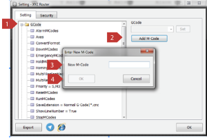
|
GCode\EmergencyMCodes |
|
If an M code or multiple M codes are defined in this section, they will be executed in case of an Emergency. To define an M code, simply type the code and press the Set button. Note that the M code must be defined under the GCode branch. To enter multiple M codes, simply separate them with commas. For example, enter “M8,M5” and then press the Set button. |
|
GCode\HoldMCodes |
|
This appears to be a duplicate of the previous message you asked me to translate. Here is the translation again: If an M code or codes are defined in this section, they will be executed during Hold functions. Note that to define an M code, you just need to write the code and press the Set button. Also note that the M code must be defined in the GCode subcategory. To enter multiple M codes, simply separate them with a comma. For example, enter “M78, M77” and then press Set. |
|
GCode\HomingMCodes |
|
If M codes are defined in this section, they will be executed during the execution of Home functions. Note that to define an M code, simply write the desired code and then press the Set button. Note that the M code must be defined under the GCode branch. To enter multiple M codes, simply separate them with a comma. For example, M8, M7, and then press the Set button. |
|
GCode\InitializeMCodes |
|
If an M code or multiple M codes are defined in this section, they will be executed at the beginning of the program. Note that to define an M code, you simply need to write the M code and then press the Set button. Keep in mind that the M code must be defined under the GCode branch. To enter multiple M codes, simply separate them with commas. For example, M8, M7, and then press the Set button. |
|
GCode\MultiFileEnabled |
|
The variable “MultiFileEnabled” is defined as True or False. If it is True, multiple files can be opened simultaneously. In other words, after selecting the desired files, they are opened in order and the next file is automatically opened after each file is finished, and it is only necessary to press the Run button to execute each file. |
|
GCode\MultiReference |
|
The variable MultiReference is defined as True or False. If it is False and no reference is specified in the GCode, the reference set in the software page will be used as the criterion and the GCode will be executed based on that reference. If it is False and a reference is specified in the GCode, the reference specified in the GCode will be used as the criterion and the entire GCode will be executed based on that reference. If it is True, the reference can be changed within the GCode. For example, it can be specified that a part of the GCode should be executed using reference G54 and another part using reference G59. In this case, the machine will be initially positioned at reference G54 and the GCode will be executed, and when it reaches the GCode line that specifies reference G59, the machine will be moved to reference G59 and the remaining GCode will be executed based on that reference. (Note that G54 and G59 are mentioned as an example.) |
|
GCode\Priority |
|
The Priority variable is used when the ShortCut variable is in the True, General branch or is determined using the RunFromHere command to specify that the program is executed from a specific line. Please note that the ShortCut variable is used as a program shortcut, meaning that if the False, ShortCut variable is used, the machine will first move to the reference point or zero position and the program will be executed from the beginning. If the ShortCut variable is True, the machine is moved to the first cutting and executable line, and the program is executed from there, taking into account the last state the machine must have for the program to run, such as the last tool used, spindle speed, or any M code specified for program execution. The order of execution for M, T, P, and S codes can be determined in the Priority section. For example, if T is written first in the Priority section, tool change is performed first, and if S is written, spindle speed is determined. In fact, the order of execution for M, T, P, and S codes is determined in this section. If the RunFromHere command is executed to specify that the program is executed from a specific line, the last state the machine must have for the program to run is taken into account. This includes the last tool used, spindle speed, or any M code specified for program execution at the specified line. The order of execution for M, T, P, and S codes can be determined in the Priority section. For example, if T is written first in the Priority section, tool change is performed first, and if S is written, spindle speed is determined. In fact, the order of execution for M, T, P, and S codes is determined in this section. |
|
GCode\ResetMCodes |
|
If M codes are defined in this section, they will be executed when the Reset functions are run. Please note that in order to define an M code, you simply need to write the desired M code and then press the Set button. Also, please note that the M code must be defined under the GCode branch. To enter multiple M codes, simply place a comma between the desired M codes, such as M10, M11, and then press the Set button. |
|
GCode\RunMCodes |
|
If M codes are defined in this section, they will be executed during the execution of the Run functions. Note that to define an M code, simply write the desired M code and then press the Set button. Note that the M code must be defined under the GCode branch. To enter multiple M codes, simply separate them with a comma. For example, M10, M11 and then press the Set button. |
|
GCode\SaveExtension |
|
In this section, you can specify the file extension for the GCode format. Note that there are several useful extensions in the list provided in this section. Alternatively, you can enter or change the GCode extension as needed by right-clicking on one of the items in the list, typing the desired extension, and then pressing the Set button. |
|
GCode\ShowLineNumber |
|
The ShowLineNumber variable is defined as True or False. If this variable is False, line numbers will not be displayed in the GCode display section (Figure 9, section 7). If this variable is True, line numbers will be displayed in the GCode display section (Figure 9, section 7). |
|
GCode\StopMCodes |
||||||||||
|
If M codes are defined in this section, they will be executed during the execution of the Stop functions. Note that to define an M code, simply write the desired M code and then press the Set button. Note that the M code must be defined under the GCode branch. To enter multiple M codes, simply separate them with a comma. For example, M10, M11 and then press the Set button. |
||||||||||
|
GCode\ToolChangerMCodes |
||||||||||
|
If M codes are defined in this section, they will be executed during the tool change operation. Note that to define an M code, simply write the desired M code and then press the Set button. Note that the M code must be defined under the GCode branch. To enter multiple M codes, simply separate them with a comma. For example, M10, M11 and then press the Set button. |
||||||||||
|
GCode\UpMCodes |
||||||||||
|
When opening GCode, if the tangent is active, this M code is used to move the Z-axis upward. Note that to define an M code, simply write the desired M code and then press the Set button. Note that the M code must be defined under the GCode branch. If a jack is used to move the Z-axis, this command is used. To enter multiple M codes, simply separate them with a comma. For example, M78, M77 and then press the Set button. |
||||||||||
|
GCode\Extension |
||||||||||
|
According to the steps in the figure above, a new extension can be added. That is, according to step 1, right-click on the Extension branch, and then according to step 2, by pressing the Add Extension button, a window called “Enter new Extension” opens, and according to step 3, the desired Extension name can be added to the window. For example, by typing “tab” and pressing OK (step 4), “tab” is added to the sub-branches of Extension.
|
||||||||||
|
GCode\Extension\[ext] |
||||||||||
|
[ext] can be any of the CNC formats (Standard G-Code), Default (Unknown files), fan (Fanuk G-Code), fgc (FGC G-Code), gc (FelexiCAM G-Code), fnc (F G-Code), Nc (NC Code), plc (GMS G-Code), tap (SolidCAM G-Code), or any other format defined by the user. If a format is not specified in the GCode, it can be opened using this format. In other words, using the Default (Unknown files) format, all GCode formats can be opened.
|
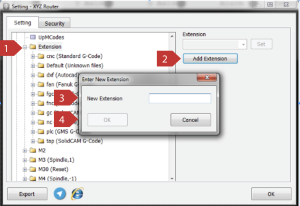
|
GCode\Extension\dxf (Autocad) |
||||||||||||||||||||||||
|
||||||||||||||||||||||||
|
GCode\Extension\dxf (Autocad)\[color] |
||||||||||||||||||||||||
|
This can refer to any of the colors Black, Blue, Cyan, Gray, Green, Magenta, Red, Silver, White, and Yellow.
|
||||||||||||||||||||||||
|
GCode\M[n] |
||||||||||||||||||||||||
|
[n] can be any of the numbers 30, 5, 4, 3, 2, or 99. In M codes, the number written next to M is the code number.
|
||||||||||||||||||||||||
|
GCode\P |
||||||||||||||||||||||||
|
||||||||||||||||||||||||
|
GCode\S |
||||||||||||||||||||||||
|
|
GCode\T |
||||||||
|
Table (8)
|
General |
|
General\DefaultReference |
|
During software startup, it is determined which reference will be the default. For example, if DefaultReference = 54, G54 reference will be used. The last reference saved through the SetReference function is stored in the DefaultReference variable. |
|
General\FeedStep |
|
This variable represents the step size for changes in the Scroll feed. By changing the FeedStep value, the amount of change per step can be determined, which is how much the Feed speed is increased or decreased for each unit of movement in the Scroll. For example, if FeedStep = 10, the Feed speed is increased or decreased by 10% for each unit of movement in the Scroll. |
|
General\FirstGoHome |
|
The FirstGoHome variable is defined as True or False. If this variable is False, FirstGoHome is generally disabled and ignored. If this variable is True, the machine is automatically moved to the Home coordinates after software startup. |
|
General\JogFeedStep |
|
This variable represents the step size for changes in the Scroll jog feed. By changing the JogFeedStep value, the amount of change per step can be determined, which is how much the JogFeed speed is increased or decreased for each unit of movement in the Scroll. For example, if JogFeedStep = 10, the JogFeed speed is increased or decreased by 10% for each unit of movement in the Scroll. |
|
General\KeepLocation |
|
KeepLocation variable is defined as True or False. If this variable is False, KeepLocation is generally disabled and ignored. If this variable is True, the last coordinates are saved if anything happens that causes the user to exit the Radonix software. When the software is used again, it will be able to execute the program from those coordinates. For example, if there is a power outage, the last position is saved and the program can be resumed from that position after the power is restored and the software is reopened. |
|
General\MaxFeed |
|
This variable is used to determine the maximum value of Scroll and Feed. By changing the value of MaxFeed, the maximum amount of Scroll and Feed can be determined. For example, if MaxFeed=100, the Scroll and Feed can be changed up to a maximum of 100% |
|
General\MaxJogFeed |
|
This variable is used to determine the maximum value of Scroll and JogFeed. By changing the value of MaxJogFeed, the maximum amount of Scroll and JogFeed can be determined. For example, if MaxJogFeed=100, the JogFeed can be changed up to a maximum of 100% in the Scroll. |
|
General\OpenRecentFile |
|
The variable OpenRecentFile is defined as True or False. If this variable is False, OpenRecentFile is generally disabled and ignored. If this variable is True, the last used file is automatically opened after starting the software. |
|
General\ParkEnabled |
|
The variable ParkEnabled is defined as True or False. If this variable is False, ParkEnabled is generally disabled and ignored. If this variable is True, the machine is automatically moved to the Park coordinates after completing the program. Note that the Park coordinates are fully explained in the General[axis]\Park address in this table, please refer to it for more information. |
|
General\ShortCut |
|
The variable ShortCut is defined as True or False. The ShortCut variable is used for program shortcuts. If this variable is False, the machine is moved to the reference point or zero point before the program starts and all codes are executed from the beginning. If this variable is True, the machine is moved to the first cutting and executable line, and the program starts. In this case, codes such as P, T, S, and M that must be used to execute the program may exist before the program starts and are checked, and the last state that the machine must have for executing the program is taken into account. For example, if the T code is placed first in the Priority section, the tool is first replaced, and if it is the S code, the spindle speed is determined, and so on, the order of execution of the P, T, S, and M codes is determined. Note that if the ShortCut variable is True in the GCode section, the Priority variable is used. |
|
General\SimpleDelay |
|
the SimpleDelay variable is completely related to the SimpleDelay function (Table 4) and the SimpleDelayPin output (Table 3), the complete process operation is explained in this section. To make it clear and understandable during the process definition, the link used is mentioned, and it is sufficient to refer to the relevant table according to the name of the pin or function and define the links. When the SimpleDelay command (link to the function) is executed, depending on the argument entered in the SimpleDelay function, the SimpleDelayPin output is turned on or off, and then a delay is created for the time set by this variable. Note that the SimpleDelay function has an argument, and when defining the SimpleDelay function, refer to Table 4. |
|
General\[axis] |
|
Please note that based on the installed interface, [axis] can be any of the X, Y, Z, A, B, C axes. All settings are the same for all axes, with the difference that the desired settings are created on the selected axis. |
|
General\[axis]\JogLocation |
|
Given that the JogLocation variable is completely related to the JogLocation parameter (Table 6) and the AJog function (Table 4), the complete functionality of the process is explained in this section. To make it clear and complete, the link used is mentioned when defining the process, and it is sufficient to refer to the relevant table and links based on the name of the parameter or function. The JogLocation variable is the destination coordinates when moving manually or, in other words, Jogging. For example, if the JogLocation value is entered as 100, the [axis] axis will be moved to coordinate 100 by running the AJog function. Note that this variable is similar to the JogLocation parameter (Table 6) with the difference that the JogLocation parameter (Table 6) has an argument for specifying the axes. Also note that, based on the installed interface, [axis] can be any of the X, Y, Z, A, B, or C axes. |
|
General\[axis]\JogMaxVelocity |
|
This variable is used to determine the maximum speed of Jog movement in the [axis] axis, and by changing the value of JogMaxVelocity, the maximum speed of Jog movement in the [axis] axis can be determined. For example, if JogMaxVelocity=100, the maximum Jog movement speed in the [axis] axis can be increased up to 100 millimeters per second. Note that according to the installed interface, [axis] can be any of the X, Y, Z, A, B, or C axes. |
|
General\[axis]\JogStep |
|
This variable is used to determine the step size in the [axis] axis during manual or Jog movement in an incremental manner. Note that this variable is similar to the JogStep parameter (Table 6), with the difference being that the JogStep parameter has an argument for determining the axes. Also note that according to the installed interface, [axis] can be any of the X, Y, Z, A, B, or C axes. |
|
General\[axis]\JogVelocity |
|
This variable is used to set the movement speed during manual or Jog movement on the [axis] axis for both Incremental and continuous modes. Note that this variable is similar to the JogVelocity parameter (Table 6) with the difference that JogVelocity parameter (Table 6) has arguments to determine the axes. Note that according to the installed interface, [axis] can be any of the X, Y, Z, A, B, or C axes. |
|
General\[axis]\Park |
|
variable is used to determine the Park coordinates. For example, if the value of Park is set to 100 and the variable ParkEnabled is active or True, after the program execution is completed, the [axis] axis will be automatically moved to coordinate 100. Note that this variable is similar to the Park parameter in Table 6, with the difference being that the Park parameter in Table 6 has arguments to determine the axes. Also note that according to the installed interface, [axis] can be any of the X, Y, Z, A, B, or C axes. |
|
General\[axis]\StopDisplacement |
|
After executing the Stop function during program execution, the [axis] axis will be displaced by the amount stored in the StopDisplacement parameter. For example, if the value of StopDisplacement is set to 10 millimeters, after executing the Stop function and the program is stopped, the [axis] axis will be automatically displaced by 10 millimeters in the positive direction. Note that according to the installed interface, [axis] can be any of the X, Y, Z, A, B, or C axes. |
Table (9)
|
JoyStick |
|||||
|
Left Trigger { LeftTriggerA, LeftTrigger+D } Right Trigger { RightTriggerA, RightTrigger+D } Left Bumper { LeftBumperD } Right Bumper { RightBumperD } Back Button { BackButtonD } Start Button { StartButtonD } X Button { XButtonD } Y Button { YButtonD } Left Stick { LeftStickButtonD, LeftStickXA, LeftStickX-D, LeftStickX+D, LeftStickYA, LeftStickY-D, LeftStickY+D } B Button { BButtonD } A Button { AButtonD } Directional Pad { DPadLeftD, DPadRightD, DPadUpD, DPadDownD } Right Stick { RightStickButtonD, RightStickXA, RightStickX-D, RightStickX+D, RightStickYA, RightStickY-D, RightStickY+D } Note that (A: Analog, D: Digital). |
|||||
|
JoyStick/Enabled |
|||||
|
The variable “Enabled” is defined as True or False. If it is False, the Joystick is generally disabled and ignored. If it is True, the Joystick is enabled. |
|||||
|
JoyStick/ExponentialTrigger |
|||||
|
The variable “ExponentialTrigger” is defined as True or False.
|
|||||
|
JoyStick/AButton/Enabled |
|||||
|
The variable “Enabled” is defined as True or False.
|
|||||
|
JoyStick/AButton/Link |
|||||
|
|||||
|
JoyStick/BackButton/Enabled |
|||||
|
The variable “Enabled” is defined as a Boolean (True or False).
|
|||||
|
JoyStick/BackButton/Link |
|||||
|
|||||
|
JoyStick/DPadLeft/Enabled |
|||||
|
The variable “Enabled” is defined as True or False.
|
|||||
|
JoyStick/DPadLeft/Link |
|||||
|
|||||
|
JoyStick/DPadRight/Enabled |
|||||
|
The variable Enabled is defined as True or False.
|
|||||
|
JoyStick/DPadRight/Link |
|||||
|
|||||
|
JoyStick/DPadUp/Enabled |
|||||
|
The variable “Enabled” is defined as a Boolean (True/False) value.
|
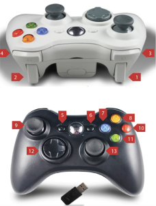
|
JoyStick/DPadUp/Link |
|||||
|
|||||
|
JoyStick/LeftBumper/Enabled |
|||||
|
The variable “Enabled” is defined as True or False.
|
|||||
|
JoyStick/LeftBumper/Link |
|||||
|
|||||
|
JoyStick/LeftStickButton/Enabled |
|||||
|
The variable Enabled is defined as True and False.
|
|||||
|
JoyStick/LeftStickButton/Link |
|||||
|
|||||
|
JoyStick/LeftStickX/Enabled |
|||||
|
The variable “Enabled” is defined as True or False.
|
|||||
|
JoyStick/LeftStickX/Link |
|||||
|
|||||
|
JoyStick/LeftStickX-/Enabled |
|||||
|
The variable Enabled is defined as True and False.
|
|||||
|
JoyStick/LeftStickX-/Link |
|||||
|
|||||
|
JoyStick/LeftStickX+/Enabled |
|||||
|
The variable Enabled is defined as True or False.
|
|
JoyStick/LeftStickX+/Link |
|||||
|
|||||
|
JoyStick/LeftStickY/Enabled |
|||||
|
The variable “Enabled” is defined as a Boolean variable, with a value of either True or False.
|
|||||
|
JoyStick/LeftStickY/Link |
|||||
|
|||||
|
JoyStick/LeftStickY-/Enabled |
|||||
|
The variable Enabled is defined as True or False.
|
|||||
|
JoyStick/LeftStickY-/Link |
|||||
|
|||||
|
JoyStick/LeftStickY+/Enabled |
|||||
|
The variable Enabled is defined as True or False. If this variable is False, LeftStickY+ is completely disabled and ignored. If this variable is True, LeftStickY+ is activated according to the specified link. |
|||||
|
JoyStick/LeftStickY+/Link |
|||||
|
|||||
|
JoyStick/LeftTrigger/Enabled |
|||||
|
The variable Enabled is defined as True and False.
|
|||||
|
JoyStick/LeftTrigger/Link |
|||||
|
|||||
|
JoyStick/LeftTrigger+/Enabled |
|||||
|
The variable “Enabled” has been defined as true and false.
|
|
JoyStick/LeftTrigger+/Link |
|||||
|
|||||
|
JoyStick/RightBumper/Enabled |
|||||
|
The variable “Enabled” is defined as True or False.
|
|||||
|
JoyStick/RightBumper/Link |
|||||
|
|||||
|
JoyStick/RightStickButton/Enabled |
|||||
|
Variable Enabled is defined as True or False.
|
|||||
|
JoyStick/RightStickButton/Link |
|||||
|
|||||
|
JoyStick/RightStickX/Enabled |
|||||
|
Variable Enabled is defined as True or False.
|
|||||
|
JoyStick/RightStickX/Link |
|||||
|
|||||
|
JoyStick/RightStickX-/Enabled |
|||||
|
Variable Enabled is defined as True or False.
|
|||||
|
JoyStick/RightStickX-/Link |
|||||
|
|||||
|
JoyStick/RightStickX+/Enabled |
|||||
|
Variable Enabled is defined as True or False.
|
|
JoyStick/RightStickX+/Link |
|||||
|
|||||
|
JoyStick/RightStickY/Enabled |
|||||
|
Variable Enabled is defined as True or False.
|
|||||
|
JoyStick/RightStickY/Link |
|||||
|
|||||
|
JoyStick/RightStickY-/Enabled |
|||||
|
Variable Enabled is defined as True or False.
|
|||||
|
JoyStick/RightStickY-/Link |
|||||
|
|||||
|
JoyStick/RightStickY+/Enabled |
|||||
|
Variable Enabled is defined as True or False.
|
|||||
|
JoyStick/RightStickY+/Link |
|||||
|
|||||
|
JoyStick/RightTrigger/Enabled |
|||||
|
Variable Enabled is defined as True or False.
|
|||||
|
JoyStick/RightTrigger/Link |
|||||
|
|||||
|
JoyStick/RightTrigger+/Enabled |
|||||
|
Variable Enabled is defined as True or False.
|
|
JoyStick/RightTrigger+/Link |
|||||
|
|||||
|
JoyStick/StartButton/Enabled |
|||||
|
Variable Enabled is defined as True or False.
|
|||||
|
JoyStick/StartButton/Link |
|||||
|
|||||
|
JoyStick/XButton/Enabled |
|||||
|
Variable Enabled is defined as True or False.
|
|||||
|
JoyStick/XButton/Link |
|||||
|
|||||
|
JoyStick/YButton/Enabled |
|||||
|
Variable Enabled is defined as True or False.
|
|||||
|
JoyStick/YButton/Link |
|||||
|
Table (10)
|
Keyboard |
|||||
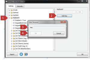
As shown in the steps illustrated in the above figure, a new Shortcut can be added. First, as per step 1, click the Keyboard branch with the left mouse button, then, as per step 2, by pressing Add Key, the Enter Key window opens, and then, as per step 3, by pressing the desired key or keys, the Shortcut is added. For example, by pressing Ctrl, Alt, and G, and then pressing the OK button (as per step 4), the new Shortcut is added to the Keyboard branch. Note that by default, several Shortcuts are defined, and by referring to the table related to the function links (Table 4), you can become familiar with the functionality of each defined Shortcut. Additionally, according to the user’s needs, a new Shortcut can be defined by selecting the desired link (Table 4) |
|||||
|
Keyboard/Enabled |
|||||
|
The Enabled variable is defined as True or False. If this variable is False, the keyboard is disabled and ignored. If it is True, the keyboard is enabled. |
|||||
|
Keyboard/KeypadBackColor |
|||||
|
This variable is used to change the background color of the Keypad window. |
|||||
|
Keyboard/KeypadEnabled |
|||||
|
The KeypadEnabled variable is defined as True or False. If this variable is False, the Keypad is disabled and ignored. If it is True, the Keypad is enabled, and you can enter or modify a number in the Value element using this window.
|
|||||
|
Keyboard/KeypadExtended |
|||||
|
The variable KeypadExtended is defined as True or False. If this variable is False, KeypadExtended is generally disabled and ignored. If this variable is True and the KeypadEnabled variable is also True, KeypadExtended is enabled, and you can enter the desired number and perform the four basic arithmetic operations (addition, subtraction, multiplication, and division) using this window.
|
|||||
|
Keyboard/[ALT]Apps (The link defined in the Link section is displayed.) / Enabled |
|||||
|
The variable “Enabled” is defined as True or False. If this variable is False, the corresponding shortcut will be disabled and ignored. If it is True and the selected link is valid, the corresponding shortcut (which involves pressing Alt and Apps keys simultaneously) will be activated based on the selected link.
According to the fact that all links in the shortcuts are fully explained in the table related to the functions (Table 4), for more information, refer to Table 4. |
|||||
|
Keyboard/[ALT]Apps (The link defined in the Link section is displayed.) / Link |
|||||
|
|||||
|
Keyboard/[ALT]D0(The link defined in the Link section is displayed.) / Enabled |
|||||
|
The variable “Enabled” is defined as True and False. If this variable is False, the desired shortcut is generally disabled and ignored. If this variable is True, the desired shortcut, which is pressing both the D0 and Apps buttons simultaneously, will be enabled based on the selected link.
|
|||||
|
|||||
|
Keyboard/[ALT]D0(The link defined in the Link section is displayed.) / Link |
|||||
|
|||||
|
Keyboard/[ALT]D1(The link defined in the Link section is displayed.) / Enabled |
|||||
|
The variable “Enabled” is defined as True and False. If this variable is False, the desired shortcut is generally disabled and ignored. If this variable is True, the desired shortcut, which is pressing both the Alt and D1 buttons simultaneously, will be enabled based on the selected link.
|
|||||
|
Keyboard/[ALT]D1(The link defined in the Link section is displayed.) / Link |
|||||
|
|||||
|
Keyboard/[ALT]Down(The link defined in the Link section is displayed.) / Enabled |
|||||
|
The variable “Enabled” is defined as True and False. If this variable is False, the desired shortcut is generally disabled and ignored. If this variable is True, the desired shortcut, which is pressing both the Alt and Down buttons simultaneously, will be enabled based on the selected link.
|
|||||
|
|||||
|
Keyboard/[ALT]Down(The link defined in the Link section is displayed.) / Link |
|||||
|
|||||
|
Keyboard/[ALT]End(The link defined in the Link section is displayed.) / Enabled |
|||||
|
The variable “Enabled” is defined as True and False. If this variable is False, the desired shortcut is generally disabled and ignored. If this variable is True, the desired shortcut, which is pressing both the Alt and End buttons simultaneously, will be enabled based on the selected link.
Considering that all the links in the shortcuts are fully described in the table related to the functions (Table 4), please refer to Table 4 for more information. |
|||||
|
Keyboard/[ALT]End(The link defined in the Link section is displayed.) / Link |
|||||
|
|||||
|
Keyboard/[ALT]Home(The link defined in the Link section is displayed.) / Enabled |
|||||
|
The variable “Enabled” is defined as True and False. If this variable is False, the desired shortcut is generally disabled and ignored. If this variable is True, the desired shortcut, which is pressing both the Alt and Home buttons simultaneously, will be enabled based on the selected link.
Considering that all the links in the shortcuts are fully described in the table related to the functions (Table 4), please refer to Table 4 for more information |
|||||
|
Keyboard/[ALT]Home(The link defined in the Link section is displayed.) / Link |
|||||
|
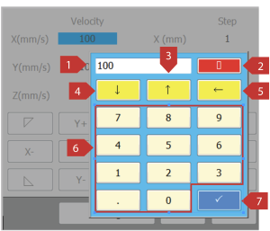
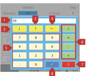
|
Keyboard/[ALT]Left(The link defined in the Link section is displayed.) / Enabled |
|||||
|
The variable “Enabled” is defined as True and False. If this variable is False, the desired shortcut is generally disabled and ignored. If this variable is True, the desired shortcut, which is pressing both the Alt and Left buttons simultaneously, will be enabled based on the selected link.
Considering that all the links in the shortcuts are fully described in the table related to the functions (Table 4), please refer to Table 4 for more information |
|||||
|
Keyboard/[ALT]Left(The link defined in the Link section is displayed.) / Link |
|||||
|
|||||
|
Keyboard/[ALT]N(The link defined in the Link section is displayed.) / Enabled |
|||||
|
The variable “Enabled” is defined as True and False. If this variable is False, the desired shortcut is generally disabled and ignored. If this variable is True, the desired shortcut, which is pressing both the Alt and N buttons simultaneously, will be enabled based on the selected link.
Considering that all the links in the shortcuts are fully described in the table related to the functions (Table 4), please refer to Table 4 for more information |
|||||
|
Keyboard/[ALT]N(The link defined in the Link section is displayed.) / Link |
|||||
|
|||||
|
Keyboard/[ALT]Next(The link defined in the Link section is displayed.) / Enabled |
|||||
|
The variable “Enabled” is defined as True and False. If this variable is False, the desired shortcut is generally disabled and ignored. If this variable is True, the desired shortcut, which is pressing both the Alt and Next (Page down) buttons simultaneously, will be enabled based on the selected link.
Considering that all the links in the shortcuts are fully described in the table related to the functions (Table 4), please refer to Table 4 for more information |
|
Keyboard/[ALT]Next(The link defined in the Link section is displayed.) / Link |
|||||
|
|||||
|
Keyboard/[ALT]OemMinus(The link defined in the Link section is displayed.) / Enabled |
|||||
|
The variable “Enabled” is defined as True and False. If this variable is False, the desired shortcut is generally disabled and ignored. If this variable is True, the desired shortcut, which is pressing both the Alt and OemMinus (-) buttons simultaneously, will be enabled based on the selected link.
Considering that all the links in the shortcuts are fully described in the table related to the functions (Table 4), please refer to Table 4 for more information |
|||||
|
Keyboard/[ALT]OemMinus(The link defined in the Link section is displayed.) / Link |
|||||
|
|||||
|
Keyboard/[ALT]Oemplus(The link defined in the Link section is displayed.) / Enabled |
|||||
|
The variable “Enabled” is defined as True and False. If this variable is False, the desired shortcut is generally disabled and ignored. If this variable is True, the desired shortcut, which is pressing both the Alt and Oemplus (+) buttons simultaneously, will be enabled based on the selected link.
Considering that all the links in the shortcuts are fully described in the table related to the functions (Table 4), please refer to Table 4 for more information |
|||||
|
Keyboard/[ALT]Oemplus(The link defined in the Link section is displayed.) / Link |
|||||
|
|||||
|
Keyboard/[ALT]Pageup(The link defined in the Link section is displayed.) / Enabled |
|||||
|
The variable “Enabled” is defined as True and False. If this variable is False, the desired shortcut is generally disabled and ignored. If this variable is True, the desired shortcut, which is pressing both the Alt and Page down buttons simultaneously, will be enabled based on the selected link.
Considering that all the links in the shortcuts are fully described in the table related to the functions (Table 4), please refer to Table 4 for more information |
|||||
|
Keyboard/[ALT]Pageup(The link defined in the Link section is displayed.) / Link |
|||||
|
|||||
|
Keyboard/[ALT]Return(The link defined in the Link section is displayed.) / Enabled |
|||||
|
The variable “Enabled” is defined as True and False. If this variable is False, the desired shortcut is generally disabled and ignored. If this variable is True, the desired shortcut, which is pressing both the Alt and Return (Enter) buttons simultaneously, will be enabled based on the selected link.
Considering that all the links in the shortcuts are fully described in the table related to the functions (Table 4), please refer to Table 4 for more information |
|||||
|
Keyboard/[ALT]Return(The link defined in the Link section is displayed.) / Link |
|||||
|
|||||
|
Keyboard/[ALT]Right(The link defined in the Link section is displayed.) / Enabled |
|||||
|
The variable “Enabled” is defined as True and False. If this variable is False, the desired shortcut is generally disabled and ignored. If this variable is True, the desired shortcut, which is pressing both the Alt and Right buttons simultaneously, will be enabled based on the selected link.
Considering that all the links in the shortcuts are fully described in the table related to the functions (Table 4), please refer to Table 4 for more information |
|
Keyboard/[ALT]Right(The link defined in the Link section is displayed.) / Link |
|||||
|
|||||
|
Keyboard/[ALT]Space(The link defined in the Link section is displayed.) / Enabled |
|||||
|
The variable “Enabled” is defined as True and False. If this variable is False, the desired shortcut is generally disabled and ignored. If this variable is True, the desired shortcut, which is pressing both the Alt and Space buttons simultaneously, will be enabled based on the selected link.
Considering that all the links in the shortcuts are fully described in the table related to the functions (Table 4), please refer to Table 4 for more information |
|||||
|
Keyboard/[ALT]Space(The link defined in the Link section is displayed.) / Link |
|||||
|
|||||
|
Keyboard/[ALT]T(The link defined in the Link section is displayed.) / Enabled |
|||||
|
The variable “Enabled” is defined as True and False. If this variable is False, the desired shortcut is generally disabled and ignored. If this variable is True, the desired shortcut, which is pressing both the Alt and T buttons simultaneously, will be enabled based on the selected link.
Considering that all the links in the shortcuts are fully described in the table related to the functions (Table 4), please refer to Table 4 for more information |
|||||
|
Keyboard/[ALT]T(The link defined in the Link section is displayed.) / Link |
|||||
|
|||||
|
Keyboard/[ALT]Up(The link defined in the Link section is displayed.) / Enabled |
|||||
|
The variable “Enabled” is defined as True and False. If this variable is False, the desired shortcut is generally disabled and ignored. If this variable is True, the desired shortcut, which is pressing both the Alt and Up buttons simultaneously, will be enabled based on the selected link.
Considering that all the links in the shortcuts are fully described in the table related to the functions (Table 4), please refer to Table 4 for more information |
|||||
|
Keyboard/[ALT]Up(The link defined in the Link section is displayed.) / Link |
|||||
|
|||||
|
Keyboard/[ALT]X(The link defined in the Link section is displayed.) / Enabled |
|||||
|
The variable “Enabled” is defined as True and False. If this variable is False, the desired shortcut is generally disabled and ignored. If this variable is True, the desired shortcut, which is pressing both the Alt and X buttons simultaneously, will be enabled based on the selected link.
Considering that all the links in the shortcuts are fully described in the table related to the functions (Table 4), please refer to Table 4 for more information |
|||||
|
Keyboard/[ALT]X(The link defined in the Link section is displayed.) / Link |
|||||
|
|
Keyboard/[ALT]Y(The link defined in the Link section is displayed.) / Enabled |
|||||
|
The variable “Enabled” is defined as True and False. If this variable is False, the desired shortcut is generally disabled and ignored. If this variable is True, the desired shortcut, which is pressing both the Alt and Y buttons simultaneously, will be enabled based on the selected link.
Considering that all the links in the shortcuts are fully described in the table related to the functions (Table 4), please refer to Table 4 for more information |
|||||
|
Keyboard/[ALT]Y(The link defined in the Link section is displayed.) / Link |
|||||
|
|||||
|
Keyboard/[ALT]Z(The link defined in the Link section is displayed.) / Enabled |
|||||
|
The variable “Enabled” is defined as True and False. If this variable is False, the desired shortcut is generally disabled and ignored. If this variable is True, the desired shortcut, which is pressing both the Alt and Z buttons simultaneously, will be enabled based on the selected link.
Considering that all the links in the shortcuts are fully described in the table related to the functions (Table 4), please refer to Table 4 for more information |
|||||
|
Keyboard/[ALT]Z(The link defined in the Link section is displayed.) / Link |
|||||
|
|||||
Table (11)
Subcategory References
|
References |
|
References\G54 |
|
This variable is used to determine and store the coordinates of the G54 reference point. |
|
References\G55 |
|
This variable is used to determine and store the coordinates of the G55 reference point. |
|
References\G56 |
|
This variable is used to determine and store the coordinates of the G56 reference point. |
|
References\G57 |
|
This variable is used to determine and store the coordinates of the G57 reference point. |
|
References\G58 |
|
This variable is used to determine and store the coordinates of the G58 reference point. |
|
References\G59 |
|
This variable is used to determine and store the coordinates of the G59 reference point. |
Table (12)
Subcategory References
Setting up the remote
To set up the remote, first connect the remote receiver to the computer via the cable. This will turn on the receiver’s internal light. Then, some settings must be made in the software in the Remote section under Settings.
Note that before connecting the cable to the computer, the USB driver with the name CDM21XXX must be installed so that the receiver can be identified by the computer after connecting the cable to the computer.

CMD21XXX installation
After downloading the CDM21228 software, double-click on the downloaded file and follow the steps below.
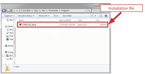
figure (2)

Figure (4)
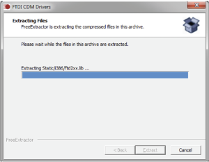
Figure (5)
Figure (6)
Figure (7)
Figure (8)
Figure (9)
Configuration
To set up the remote, a series of software settings must be performed. In the CAM-Pro software, enter the Remote section from the Settings menu, open the Remote branch, and you will see 4 sub-branches. (Figure 10)
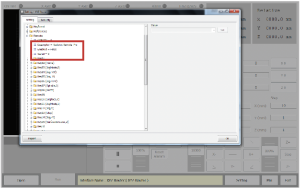
Figure (10)
|
Remote |
|||||
|
Remote/Channel |
|||||
|
This variable is used to determine the remote channel. The remote channel is a number between 1 and 32 that needs to be entered in this section. How to change the remote transmitter channel: There are 32 buttons on the transmitter with corresponding numbers, as shown in the figure below, that the operator can use to select the transmitter channel. The method for doing this is as follows: First, simultaneously press the two buttons named Reset and Pause (marked with the abbreviations RST and ||) in the last row of the transmitter buttons. The red light on the transmitter will start flashing continuously, and after a few seconds, the light will turn on uniformly. Then, release the buttons, and by pressing any of the keyboard buttons with the corresponding number, it will be saved as the new remote channel. (The number corresponding to each button is written next to that button in the figure. For example, F12 corresponds to button number 9.) In the last step, the selected new number should be entered in this Channel section to set the new channel completely.
|
|||||
|
Remote/Descriptor |
|||||
|
This variable is used to determine the type of remote. In fact, through this section, it can be specified whether the remote is related to the Pro or Plus controller model. |
|||||
|
Remote/Enabled |
|||||
|
The Enabled variable is defined as True and False. If this variable is False, the remote is disabled completely and ignored. If this variable is True, the remote is activated. |
|||||
|
Remote/Serial |
|||||
|
This variable is used to determine the remote serial number. In fact, the remote serial is a 5-digit code that is located on the back of each remote. Each remote has a different serial number. |
|||||
|
Remote/Key[n] |
|||||
|
Since all Remote sub-branches from Key01 to Key32 have a common definition, Key[n] is used to provide a comprehensive definition for all Remote sub-branches. In fact, [n] can be any number from 1 to 32. There are 32 buttons on the transmitter, each of which can be defined based on its button number. (The button numbers are provided in this table in the explanations of the Channel sub-branch). Therefore, if any number from 1 to 32 is used instead of [n], it will be the identifier of the Remote sub-branches and button number. |
|||||
|
Remote/Key[n]/Enabled |
|||||
|
The Enabled variable is defined as True and False. If this variable is False, the remote button is disabled completely and ignored. If this variable is True, the button on the remote is activated based on the specified link. For example, if Key02 is True in the Enabled section, button number 2 will be activated. |
|||||
|
Remote/Key[n]/Link |
|||||
|
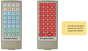
Table(13)
Subcategory Router
|
Router |
|
Router\KeepZUp |
|
This variable is used to determine the distance of the Z-axis from the reference point when the machine axes are moved to the reference point. For example, if the entered number is 0.0, the Z-axis will be located at the reference point. If the entered number is 20, the Z-axis will move 20 units in the positive direction from the reference point. |
|
Router\SafeZ |
|
Generally, when moving the axes, the Z-axis is moved to its highest point and after moving the other axes, it moves to the desired point. With this variable, instead of moving the Z-axis to its highest point, it moves up or down from the reference point by the SafeZ value For example, if the highest point of the Z-axis is 0 and the lowest point is 250 and this variable is set to 100, the machine will move the Z-axis 100 units up from the reference point instead of moving it to its highest point. |
|
Router\SpindleAutoOff |
|
This variable is used for GCodes that do not have an M-code to turn off the spindle. The SpindleAutoOff variable is defined as True or False. If this variable is False, SpindleAutoOff is generally disabled and ignored. If this variable is True, SpindleAutoOff is enabled, and at the end of executing the GCode, the spindle is automatically turned off. |
|
Router\SpindleAutoOn |
|
This variable is used for GCodes that do not have an M-code to turn on the spindle. The SpindleAutoOn variable is defined as True or False. If this variable is False, SpindleAutoOn is generally disabled and ignored. If this variable is True, SpindleAutoOn is enabled, and during the execution of the GCode, the spindle is automatically turned on. |
|
Router\SpindleDelay |
|
This variable is used to set the delay time for the spindle to reach the desired speed or stop. The unit for this variable is milliseconds. |
|
Router\SpindleMaxSpeed |
|
This variable is used to determine the maximum speed that can be set for the spindle. |
|
Router\ SpindleMinSpeed |
|
This variable is used to determine the minimum speed that can be set for the spindle. |
|
Router\ SpindleSpeed |
|
This variable is used to store the speed value set for the spindle. For example, if the user sets the Scroll for spindle speed to 18000, the number 18000 is stored in this variable. |
|
Router\SpindleSpeedStep |
|
This variable determines the step change for the SpindleSpeed when using the Scroll. By changing the value of SpindleSpeedStep, the amount of change for each step can be determined. For example, if SpindleSpeedStep is set to 2000, the spindle speed will change by 2000 for each unit of movement in the Scroll. |
|
RS485 |
|||||
|
This branch can be used if an analog module with four analog inputs is used. In fact, by connecting the analog module to the RS485 port of the controller, all four analog sub-branches can be used in the RS485 branch.
|
|||||
|
RS485\Enabled |
|||||
|
The Enabled variable is defined as True and False. If this variable is False, the RS485 branch is generally disabled and ignored. If this variable is True, the RS485 branch is activated. |
|||||
|
RS485\AnalogInput |
|||||
|
Note that if the link defined for the analog module input is similar to the link for the Scroll on the software page, the Scroll is deactivated. For example, if a volume is connected to the analog module and a link is defined for it so that the spindle speed can be controlled through that link, then the Scroll defined for changing the spindle speed is automatically deactivated. |
|||||
|
RS485\AnalogInput\Analog[n]\Enabled |
|||||
|
There are four analog inputs on the analog module, so instead of [n], any number from 1 to 4 can be used. In fact, because all the AnalogInput sub-branches from Analog1 to Analog4 have a common definition, Analog[n] is used. The AnalogX variable is defined as True and False. If this variable is False, the analog input is generally disabled and ignored. If this variable is True, the analog input is activated according to the defined link. For example, if Analog2 is True in the Enabled section, Analog 2 is activated. |
|||||
|
RS485\AnalogInput\Analog[n]\Link |
|||||
|
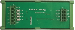
table (15)
Subcategory System
- All fundamental system variables are located in this branch. Therefore, this section is highly sensitive and illogical changes may disrupt program execution or damage the machine’s mechanics.
|
System |
||||||||||||||
|
System\AlarmEnabled |
||||||||||||||
|
The variable AlarmEnabled is defined as True or False. If it is False, AlarmEnabled is generally inactive and ignored. If it is True and the wiring for the alarm motors is done correctly (as described in chapter two), then if the motors have an alarm, the alarm is triggered. Additionally, if the wiring for the alarm section is incorrect or not done, the alarm is triggered again. Note that in the event of an error in any axis, all axes will stop. Also note that in the motor stop command, as there is no alarm output, the variable AlarmEnabled must be set to False. |
||||||||||||||
|
System\Connection |
||||||||||||||
|
This variable is used to determine the type of connection between the controller and the computer and can be defined as LAN or USB depending on the type of controller used. |
||||||||||||||
|
System\EmergencyType |
||||||||||||||
|
This variable is used to determine the operation that occurs when the Emergency button is pressed.
|
||||||||||||||
|
System\HomeNecessary |
||||||||||||||
|
This variable is used to determine the importance of having a Home position for the device.
|
||||||||||||||
|
System\HomeOrder |
||||||||||||||
|
This variable is used to determine the order in which the axes are homed. For example, Z,XY, where in this case the Z axis is homed first, and after the Z axis homing is complete, the X and Y axes are homed simultaneously. If there is a comma between the axes, the axes are homed separately and in the order specified. For example, Z,X,Y, where in this case the Z axis is homed first, and after the Z axis homing is complete, the X axis is homed, and finally, the Y axis is homed. If there is no comma between the axes, the axes are homed simultaneously. For example, ZXY, where in this case the Z, X, and Y axes are homed simultaneously. |
||||||||||||||
|
System\PulseDivider |
||||||||||||||
|
This variable is used to divide the output pulses of the controller into specific numbers. It is used to create a proportion between the pulse rate of the controller and the motors. In other words, the pulse rate of the controller is 500 kilopulses, and there are motors that have a lower pulse rate, which can cause problems. For example, if the pulse rate of a servo motor is 200 kilopulses, the pulses should be divided by 4 so that the pulse rate of the controller becomes 125 kilopulses. Another example is when using stepper motors with a pulse rate of 100 kilopulses, the value of 8 should be selected for PulseDivider so that the stepper motor can read the pulse rate of the controller. |
||||||||||||||
|
System\Analogs\Analog[n]\Enabeld |
||||||||||||||
|
[n] refers to the number 1 and 2, which determine the output pins of the analog. The Enabled variable is defined as True or False. If this variable is False, the Analog[n] port is generally disabled and ignored. If this variable is True, the Analog[n] port is enabled and can be used according to the specified link. |
||||||||||||||
|
System\Analogs\Analogs[n]\Link |
||||||||||||||
|
||||||||||||||
|
System\Axes\Axes[n]\Acceleration |
||||||||||||||
|
[n] is an identifier number between 1 to 6 that determines the axis number. Note that it is not allowed to have an inactive axis between active axes. This variable is used to determine the axis movement acceleration in terms of units/s2. The value of this variable does not affect the acceleration of the program execution by ToolPath. The appropriate value for this variable is determined by considering the stiffness, axis weight, and motor power. In general, it can be said that stiffness and axis weight have an inverse relationship, and motor power has a direct relationship with the value of this variable. The value that can be defined for this variable is a number between 10 and 30,000. |
||||||||||||||
|
System\Axes\Axes[n]\AlarmEnabled |
||||||||||||||
|
n] refers to a number between 1 and 6 that determines the axis number. Note that a disabled axis cannot be present among the active axes. If the AlarmEnabled variable is active in the System\AlarmEnabled address in this table, this variable will be taken into account. The AlarmEnabled variable is defined as True or False. If this variable is False, the AlarmEnabled of the corresponding axis is disabled and ignored. If this variable is True, the AlarmEnabled of the corresponding axis is enabled, and if the motor alarm part of the axis is correctly wired (according to section two), if the axis has an alarm, it will be displayed. Also, if wiring of the alarm section is incorrect or not wired, the alarm of the corresponding axis will turn on again. Note that in stepper motors, since there is no alarm output, the AlarmEnabled variable must be set to False. |
|
System\Axes\Axes[n]\Backlash |
|
[ n] is a number between 1 and 6, which determines the axis number. Note that there cannot be any inactive axes among the active ones. If the axis has mechanical backlash, this variable can be used to approximately neutralize its effect. This value should be the average backlash over the length of the axis, in terms of the unit used for that axis. The value that can be defined for this variable is a number between 0 and 1. |
|
System\Axes\Axes[n]\Direction |
|
[n] is a number between 1 and 6 which specifies the axis number. Note that there should not be any inactive axes among the active ones. This variable is used to determine the direction of axis movement. It is better for axis movement directions to comply with international standards. The right-hand rule can be used to determine the correct direction of axes.
The value that can be defined for this variable is Negative or Positive. |
|
System\Axes\Axes[n]\Enabled |
|
[n] is a number between 1 and 6 that identifies the axis number. Note that it is not allowed to have a disabled axis among the active ones. The variable Enabled is defined as True or False. If it is False, the axis will generally be disabled and ignored. If it is True, the axis will be enabled. Note that the axes must be enabled in order. For example, you cannot enable axes 1 and 3 while disabling axis 2; instead, you must enable axes 1 and 2 and disable axis 3. |
|
System\Axes\Axes[n]\HomeDetectVelocity |
|
[n] is a number between 1 and 6 that identifies the axis number. Note that it is not allowed to have a disabled axis among the active ones. This variable is used to determine the speed of the axis after the home sensor is detected. The value of this variable should not be too high to give the sensor enough time to accurately determine the home point. After the home sensor is detected, the axis moves in the opposite direction of the home sensor until the sensor is released. |
|
System\Axes\Axes[n]\HomeDirection |
|
[n] is a number between 1 and 6 that identifies the axis number. Note that it is not allowed to have a disabled axis among the active ones. This variable is used to determine the direction of axis movement towards the home sensor. Therefore, using this variable, the location of the home sensor can be defined. The value that can be defined for this variable is Negative or Positive. |
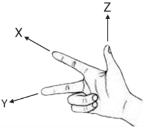
|
System\Axes\Axes[n]\HomeDisplace |
|
[n] is a number between 1 and 6 that identifies the axis number. Note that it is not allowed to have a disabled axis among the active ones. This variable determines the displacement of the axis home point after homing. |
|
System\Axes\Axes[n]\HomeFastVelocity |
|
[n] is a number between 1 and 6 that determines the axis number. Note that among the active axes, the presence of an inactive axis is not allowed. If high speed is required when homing, the speed value is determined by this variable. Please note that adding a sensor is required to execute this variable. In fact, the first home sensor is for HomeFastVelocity and the second home sensor is for HomeVelocity. |
|
System\Axes\Axes[n]\HomeLocation |
|
[n] is a number between 1 and 6 that determines the axis number. Note that among the active axes, the presence of an inactive axis is not allowed. This variable is used to determine the coordinates of the home point after the home sensor is activated. In other words, if the position of the home point is something other than MinCourse or MaxCourse, the numerical value of the home point can be determined by this variable. |
|
System\Axes\Axes[n]\HomeVelocity |
|
[n] is a number between 1 and 6 that determines the axis number. Note that among the active axes, the presence of an inactive axis is not allowed. The homing speed can be determined by this variable. 109 |
|
System\Axes\Axes[n]\MaxCourse |
|
[n] is a number between 1 and 6 that determines the axis number. Note that among the active axes, the presence of an inactive axis is not allowed. This variable is used to determine the maximum course that the axis can have. In other words, after homing, this value will be the upper limit of the axis and the axis will not go beyond this limit. The value that can be defined for this variable is a number between -109 and 109. |
|
System\Axes\Axes[n]\MaxCourseGrid |
|
[n] is a number between 1 and 6 that determines the axis number. Note that among the active axes, the presence of an inactive axis is not allowed. This variable is used to determine the display of the maximum course of guide lines in ToolPath before homing or when the device does not need to be homed. In other words, the upper limit of the guide line display is determined by this variable before homing or when the device does not need to be homed. The value that can be defined for this variable is a number between -109 and 109. |
|
System\Axes\Axes[n]\MaxVelocity |
|
[n] is a number between 1 and 6 that determines the axis number. Note that among the active axes, the presence of an inactive axis is not allowed. This variable determines the maximum allowed speed for axis movement. This value affects the speed of the axis under all conditions. If no value is considered for this variable, the maximum possible speed for this axis will be considered. |
|
System\Axes\Axes[n]\MinCourse |
|
[n] is a number between 1 and 6 that determines the axis number. Note that among the active axes, the presence of an inactive axis is not allowed. This variable is used to determine the minimum course that the axis can have. In other words, after homing, this value will be the lower limit of the axis and the axis will not go below this limit. The value that can be defined for this variable is a number between -109 and 109. |
|
System\Axes\Axes[n]\MinCourseGrid |
|
[n] is a number between 1 and 6 that specifies the axis number. Note that there is no permissible inactive axis among the active axes. This variable is used to determine the minimum display range of guide lines in ToolPath before homing or in cases where the device does not need to be homed. In other words, this variable determines the lower limit of the guide line display range before homing or in cases where the device does not need to be homed. The value that can be defined for this variable is a number between -109 and 109 |
|
System\Axes\Axes[n]\Name |
|
[n] is a number between 1 and 6 that specifies the axis number. Note that there is no permissible inactive axis among the active axes. This variable determines the name of the axis. Note that the axis name can be one of the letters X, Y, Z, U, V, W, A, B, and C. |
|
System\Axes\Axes[n]\Rotary |
|
[n] is a number between 1 and 6 that specifies the axis number. Note that there is no permissible inactive axis among the active axes. The Rotary variable is defined as True or False. If this variable is False, the movement of the axis is considered to be linear. If this variable is True, the movement of the axis is considered to be rotary. Note that if a rotary motion axis is selected, the movement of the axes is not limited by MinCourse and MaxCourse, and in displacements, values outside this range are transferred to within the range while maintaining the position. |
|
System\Axes\Axes[n]\RundTrip |
|
[n] is a number between 1 and 6 that specifies the axis number. Note that there is no permissible inactive axis among the active axes. The RundTrip variable is defined as True or False. If this variable is False, RundTrip is generally disabled and ignored. If this variable is True, when moving, the axis is first moved to the highest defined point, then the other axes are moved to the specified position, and finally the axis is moved to the specified position. For example, in router devices, if the RundTrip variable is True in Axes3, when moving the axes, the Z-axis is first moved to the highest point, then the X and Y axes are moved to the specified position, and finally the Z-axis is moved to the specified position. |
|
System\Axes\Axes[n]\SameAs |
|
[n] is a number identifier between 1 and 6, determining the axis number. Note that inactive axes are not allowed among active axes. This variable can be used to connect the pulse output of an axis to a specific axis and create identical axes. The value of this variable is equal to the name or number of the axis to which this axis is to be connected. If movement in the opposite direction of the desired axis is necessary, a negative sign is used before the name and number of that axis. It is usually used when there is more than one motor in an axis. Note that the axis for which the SameAs parameter is defined must be the last axis or Axis. |
|
System\Axes\Axes[n]\Step |
|||||
|
[n] is a number identifier between 1 and 6, determining the axis number. Note that inactive axes are not allowed among active axes. This variable indicates the movement value of the axis per pulse in the desired unit of measure. In fact, the adaptation of axis movement sizes to movement sizes based on one of the standard units is done by this variable, which is also called calibration. For example, it can be determined that 1 unit of movement of the desired axis is equal to 1 millimeter, 1 centimeter, 1 inch, etc. This variable is obtained either through measurement and proportion or by calculation. Calculation is certainly a more accurate and reliable method that requires information about the drives and motion transfer system. A software called Radonix Calibrator is provided for measuring this variable, which easily provides calibration. (Please refer to Chapter 5 for more information.) |
|||||
|
System\Axes\Axes[n]\Unit |
|||||
|
[n] is a number between 1 and 6 which determines the axis number. Note that inactive axes are not allowed among active axes. This variable is a string used to display the measurement unit. This variable does not affect internal interface calculations and is only used for display purposes. |
|||||
|
System\InPorts\InPort[n]\Enabled |
|||||
|
[n] is the identifier for the pin number of the digital inputs of the controller. The variable “Enabled” is defined as True or False. If this variable is False, the input port in question is generally deactivated and ignored. If this variable is True, the input port in question is activated and can be used according to the designated link. |
|||||
|
System\InPorts\InPort[nn]\Link |
|||||
|
|||||
|
System\InPorts\InPort[n]\NC |
|||||
|
[n] refers to the pin number of the digital inputs/outputs of the controller. The variable “Enabled” is defined as either True or False. If this variable is False or undefined, the input port is considered normally open. If this variable is True, the input port is considered normally closed. |
|||||
|
System\OutPorts\OutPort[n]\Enabled |
|||||
|
[n] refers to the pin number of the digital outputs of the controller. The variable “Enabled” is defined as either True or False. If this variable is False, the output port is generally disabled and ignored. If this variable is True, the output port is activated and can be used according to the specified link. |
|||||
|
System\OutPorts\OutPort[n]\Link |
|||||
|
|||||
|
System\OutPorts\OutPort[n]\NC |
|||||
|
[n] refers to the pin number of digital input/output ports of the controller. The variable “Enabled” is defined as True or False. If this variable is False or undefined, the input/output port is considered as Normally Open. If this variable is True, the input/output port is considered as Normally Closed. |
|
System\OutPorts\OutPort[n]\NC |
||||||
|
[n] refers to the pin number of digital input/output ports of the controller. The variable “Enabled” is defined as True or False. If this variable is False or undefined, the input/output port is considered as Normally Open. If this variable is True, the input/output port is considered as Normally Closed. |
||||||
|
System\ToolPath\Acceleration |
||||||
|
This variable is used to determine the acceleration of the axes simultaneously during program execution in units of unit/s. The appropriate value for this variable is determined taking into account the inertia, axis weight, and motor power. This value can be calculated mechanically and approximately. Generally, it can be said that there is an inverse relationship between inertia and axis weight and a direct relationship between motor power and the value of this variable. The value that can be defined for this variable is a number between 10 and 30000. |
||||||
|
System\ToolPath\Axes |
||||||
|
This variable determines the axes used in ToolPath that have simultaneous movement (Interpolate). Note that the names of the axes must be separated from each other by commas (,). |
||||||
|
System\ToolPath\FeedVelocity |
||||||
|
When the Feed or F value is not defined in the GCode, the value specified in this variable is used as the basis for the movement speed. |
||||||
|
System\ToolPath\FeedVector |
||||||
|
If this variable has no value, all axes in the ToolPath with Interpolate motion will calculate in the movement speed. The axes listed in this variable are used in calculating the movement speed for Interpolate motion. |
||||||
|
System\ToolPath\Focus |
||||||
|
The Focus variable is defined as True or False. If this variable is False or has no value, the display is centered on the desktop and the layout is displayed on the entire screen when the executable file is opened. If this variable is True, the display is centered on the layout and the layout is displayed on the entire screen when the executable file is opened. |
||||||
|
System\ToolPath\JunctionFactor |
||||||
|
Software programs that convert motion paths into G-code usually simulate curved paths using line segments. There are angles between these lines, and based on these angles, the length of the lines, and the motion acceleration defined for the ToolPath, the maximum speed allowed for passing these intersections is calculated. This variable is actually a coefficient that is multiplied by the calculated maximum speed. Values greater than 1 are used in cases where the motion acceleration is low or the device is capable of passing intersections at a higher speed. The value that can be defined for this variable is a number between 1 and 100. |
||||||
|
System\ToolPath\LastView |
||||||
|
There are three general structures for displaying LastView, as follows:
|
|
System\ToolPath\MinLineLength |
||||||
|
When this parameter is zero, the averages of the steps are merged and a vector is obtained. In other words, if this parameter is zero, 10 times the merging of steps is considered as the smallest linear value that should be accepted, and by doing so, smaller lines than that value are ignored and connected to the next line. For example, if the steps are 1 millimeter and this parameter is zero, 10 times the steps are considered as the smallest value, meaning lines smaller than 0.1 millimeters are connected to the next line, while lines 0.1 millimeters or larger are executed without any change. |
||||||
|
System\ToolPath\Smoothness |
||||||
|
This variable is used to create a smoother and more uniform motion. In fact, the velocity curve changes from linear to an S-curve. As the value of this variable increases, the curvature of the S-curve also increases. If the speed or acceleration of the device is high, it is better not to set the value of this variable too high. The value that can be defined for this variable is a number between 1 and 250 milliseconds. |
||||||
|
System\ToolPath\TraverseAcceleration |
||||||
|
This variable is used to determine the axis displacement acceleration in units of unit/s² without running the program. The appropriate value for this variable is determined based on the stiffness, axis weight, and motor power. This value can be mechanically and approximately calculated. Generally, it can be said that stiffness and axis weight have an inverse relationship, and motor power has a direct relationship with the value of this variable. The value that can be defined for this variable is a number between 10 and 30000. |
||||||
|
System\ToolPath\TraverseVelocity |
||||||
|
This variable is used to determine the axis displacement speed without running the program, as well as during displacement using G0. |
||||||
|
System\ToolPath\View |
||||||
|
This variable determines the axes that are visible in the ToolPath. Only the combination of the display in the interface is determined in this variable, and the names X, Y, Z, C, A, and B must be used in these combinations. The axes used in the ToolPath are displayed in the order of the axes written in this variable. The number of axes in this variable should not exceed the number of axes used in the ToolPath. Three general structures, along with the axis order in the interface, have been considered for displaying ToolPath, as follows:
|
Table(16)
Subcategory Timer
|
Timer |
|
According to the steps shown in the above figure, a new timer can be added. In other words, in step 1, the left-click of the mouse is pressed on the Timer branch, and then in step 2, by pressing Add Timer, a window called Enter Timer Name opens, which in step 3, the desired name can be selected for the new timer, for example, by writing T1 and pressing the OK button (according to step 4), the new timer is added to the Timer sub-branches. |
|
Timer\[n]\Automatic |
|
The variable “Automatic” is defined as True or False. If this variable is False, the timer command is issued using the RunTimer and StopTimer functions in the function link (Table No. 4), and after executing the timer command, the timer is executed according to the link specified in the Link section. If this variable is True, the timer is automatically executed during program execution according to the specified link. The RunTimer and StopTimer functions are fully explained in the function link table (Table No. 4). Please refer to Table No. 4 for more information. |
|
Timer\[n]\Continuouse |
|
The variable “Continuous” is defined as True or False. If this variable is False, the timer is executed only once. If this variable is True, the timer is repeated multiple times as long as the condition specified in the ControlStatusCondition variable is met. |
|
Timer\[n]\ControlStatusCondition |
|
There is a variable called ControlStatusCondition which is used to determine the condition for executing the timer. By entering one of the ControlStatus arguments (parameter link) in the ControlStatusCondition variable, it can be determined under what conditions the timer should be executed. For example, if ControlStatusCondition is set to 1, the timer will only run when the software is online. The ControlStatus parameter is fully explained in the parameter link table. For more information, please refer to table (6). Note that only one argument or condition can be defined for the ControlStatusCondition variable. |
|
Timer\[n]\Duration |
|
The variable “Duration” is used to determine the length of time for the timer in milliseconds. In other words, after issuing the command to run the timer (either automatically or manually), the timer will run for the time set in the “Interval” variable and then for the time set in the “Duration” variable. For example, if the “Duration” variable is set to 5000, after issuing the command to run the timer and after the time set in the “Interval” variable has passed, the timer will run for 5 seconds and then turn off. |
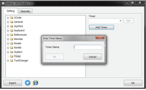
|
Timer\[n]\Enabled |
|||||
|
The variable “Enabled” is defined as True and False. If it is False, the timer is generally disabled and ignored. If it is True, the timer is enabled and can be used based on the defined variables and links. |
|||||
|
Timer\[n]\Interval |
|||||
|
This variable is used to determine the start time of the timer in milliseconds. In other words, after issuing the command to run the timer (either automatically or manually), the timer will run after the time set in the Interval parameter has elapsed. For example, if Interval = 60000, the timer will run after 60 seconds have passed following the issuance of the command to run the timer. If the Continuouse variable in the Timer[n] address in the same table is active, this process will be repeated. |
|||||
|
Timer\[n]\Link |
|||||
|
Table(17)
Subcategory ToolChanger
|
ToolChanger |
|
ToolChanger\AutoSetToolHeight |
|
The variable “AutoSetToolHeight” is defined as True or False. If this variable is False, AutoSetToolHeight is generally disabled and ignored. If it is True, AutoSetToolHeight is activated, and when the tool is changed, the tool height is first registered using a height detection sensor, and then the tool is changed. This process is performed every time the tool change command is issued. |
|
ToolChanger\ClampDepth |
|
This variable is used to determine the height of the tool holder’s collet. In fact, if the tool holder’s collet is not of the pressure type and the tool is placed in the collet, the value of the collet’s height is determined by this variable. The value that can be defined for this variable is a number between 0 to 100 millimeters. |
|
ToolChanger\CurrentTool |
|
This variable stores the current tool number. |
|
ToolChanger\DefaultTool |
|
This variable is used to determine the active tool as default. In other words, if for structural reasons, a specific tool must be considered as the active tool when opening the program, this variable is used to specify the number of the active tool. Note that this variable is specific to certain devices and usually has no value, meaning it should be empty. |
|
ToolChanger\Enabled |
|
The Enabled variable is defined as True or False. If this variable is False or undefined, the ToolChanger or automatic tool change is generally disabled and ignored. If this variable is True, the ToolChanger or automatic tool change is enabled. |
|
ToolChanger\GoSafeLocation |
|
The variable “GoSafeLocation” is defined as True or False. If this variable is False, “GoSafeLocation” is generally disabled and ignored. If this variable is True, “GoSafeLocation” is enabled. This variable is used when it is necessary to move the machine to a safe coordinate before changing the tool. After moving to the safe point, the tool change will be executed. This variable is usually used for machines that have a parking cover. |
|
ToolChanger\Jack3Delay |
|
In devices that use a jack for tool changing, this variable is defined. In fact, if the start, end, or both ends of the jack have not been used with the end-of-path detection sensor input T-Jack3SensorPin, this variable is used to create the required delay to complete the jack movement. In other words, if the input T-Jack3SensorPin has not been used, the Jack3Delay variable is activated, which can determine the delay time for turning on and off the T-Jack3Pin output. Note that this variable is used when the end-of-path detection sensor and input T-Jack3SensorPin are not used in the device because the sensor takes priority over the Jack3Delay variable if it exists. This variable is related to the input T-Jack3SensorPin and output T-Jack3Pin. For more information, refer to tables 2 and 3. |
|
ToolChanger\JackDelay |
|
In devices that use a jack for tool changing, this variable is defined. In fact, if the start, end, or both ends of the jack have not been used with the end-of-path detection sensor input T-JackSensorPin, this variable is used to create the required delay to complete the jack movement. In other words, if the input T-JackSensorPin has not been used, the JackDelay variable is activated, which can determine the delay time for turning on and off the T-JackPin output. Note that this variable is used when the end-of-path detection sensor and input T-JackSensorPin are not used in the device because the sensor takes priority over the JackDelay variable if it exists. This variable is related to the input T-JackSensorPin and output T-JackPin. For more information, refer to tables 2 and 3. |
|
ToolChanger\RotationSensorPeriod |
||||||||||||||||||||||||||||||||||||||||||
|
This variable is used to detect spindle rotation stoppage. In fact, a time period for checking spindle rotation is determined by this variable. For example, if the value of this variable is 1000, if no signal is sent from the spindle rotation sensor input for one second, it is considered as spindle rotation stoppage. |
||||||||||||||||||||||||||||||||||||||||||
|
ToolChanger\SpindleOffDelay |
||||||||||||||||||||||||||||||||||||||||||
|
This variable is used to determine the delay time until the spindle stops during a tool change. If this variable does not have a value, its value is taken from the SpindleDelay variable in the Router branch. Note that if the spindle has one of the sensors (T-HSD-S3Pin, T-CC-S3Pin, T-TEKNO-S3Pin, T-SpindleRotationSensorPin, T-InverterStopPin), this variable will be ignored |
||||||||||||||||||||||||||||||||||||||||||
|
ToolChanger\ToolHolderDelay |
||||||||||||||||||||||||||||||||||||||||||
|
A delay is set to allow the internal jack of the spindle enough time to grip or release the tool. This time is determined by the ToolHolderDelay variable. |
||||||||||||||||||||||||||||||||||||||||||
|
ToolChanger\ToolsInCourse |
||||||||||||||||||||||||||||||||||||||||||
|
The ToolsInCourse variable is defined as True or False. If this variable is False, ToolsInCourse is disabled. If this variable is True, ToolsInCourse is enabled and the operator can exit after taking Home and determining the maximum and minimum courses during the Home operation. This is used when the machine parking is outside the Home coordinates and table limits, and the user wants to obtain the coordinates of each tool for automatic tool change. Note that after the settings are done, this variable should be set to False. |
||||||||||||||||||||||||||||||||||||||||||
|
ToolChanger\Type |
||||||||||||||||||||||||||||||||||||||||||
|
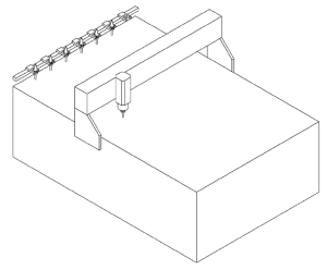
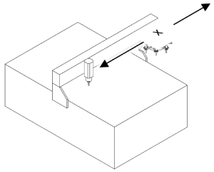
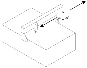
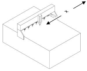
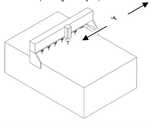
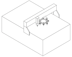
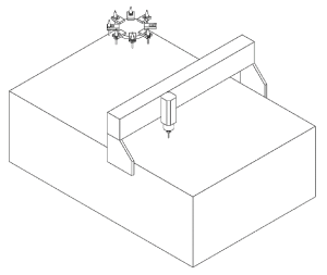
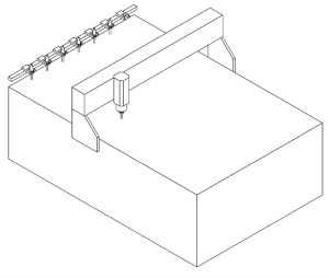
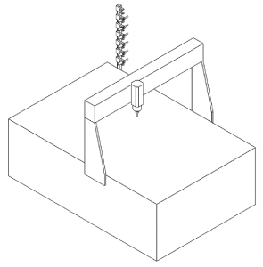
|
ToolChanger\Velocity |
|
This variable is used to determine the speed of tool changing. In fact, the entry and exit speed of the parking area can be specified. |
|
ToolChanger\Displacement\X |
|
The displacement value of the X-axis is determined by these variables for extracting the tool from the clamp. The reverse process is also done when releasing the tool inside the clamp. Note that the value entered in this variable should be relative to the parking area. ToolChanger\Displacement\Y |
|
ToolChanger\Displacement\Y |
|
The displacement value of the Y-axis is determined by these variables for extracting the tool from the clamp. The reverse process is also done when releasing the tool inside the clamp. Note that the value entered in this variable should be relative to the parking area. |
|
ToolChanger\Displacement\Z |
|
After releasing the tool inside the clamp, the Z-axis rises by the value set for this variable and then moves towards the next tool. The reverse process is also done when grabbing the tool inside the clamp. The value of spindle rise should be such that there is a logical distance from the other tools. |
|
ToolChanger\SafeLocation\X |
|
If the GoSafeLocation variable is True, a sub-branch called SafeLocation is added to the ToolChanger branch. When using this variable, before changing the tool, the device is moved to the point specified by this variable along the X axis and after moving to the safe point, the tool change is performed. Note that this variable is defined with respect to the home point of the device. |
|
ToolChanger\SafeLocation\Y |
|
ToolChanger\SafeLocation\Y If the GoSafeLocation variable is True, a sub-branch called SafeLocation is added to the ToolChanger branch. When using this variable, before changing the tool, the device is moved to the point specified by this variable along the Y axis and after moving to the safe point, the tool change is performed. Note that this variable is defined with respect to the home point of the device. |
|
ToolChanger\ToolHeightSensor\Velocity |
|
This variable is used to determine the speed of movement towards the tool height sensor. The device moves at the speed set in the TraverseVelocity variable (located in the System branch and ToolPath sub-branch) towards the coordinates of the tool height sensor. In fact, at the beginning of the tool height measurement process, the device is moved at the TraverseVelocity speed to the height specified by the Z variable in the ToolChanger branch and ToolHeightSensor sub-branch and then moves at the speed specified in this variable. A lower value of this speed increases accuracy but also increases measurement time. |
|
ToolChanger\ToolHeightSensor\X |
|
This variable determines the coordinates of the installation location of the height measurement sensor along the X axis. |
|
ToolChanger\ToolHeightSensor\Y |
|
This variable determines the coordinates of the installation location of the height measurement sensor along the Y axis. |
|
ToolChanger\ToolHeightSensor\Z |
|
This variable determines the starting coordinates of movement towards the sensor along the Z axis, after which the Z axis moves at the speed specified in the Velocity parameter at the ToolChanger\ToolHeightSensor address. |
|
ToolChanger\Tools\ToolReference |
|
The coordinates on which the tool height sensor measures the tool height. If the tool height measurement process is performed with the empty collet and tool number zero, this variable is automatically set and in this case, the tool height is the actual height from the collet surface. The default value of this variable is zero and if the height sensor is used, there is no need to set this variable. |
|
ToolChanger\Tools\Tool[n]\Enabled |
|
n refers to the tool number, which is a number between 1 and 64. The variable Enabled is defined as True or False. If this variable is False, the tool is disabled and ignored in general. If this variable is True, the tool is enabled and can be used in automatic tool change. |
|
ToolChanger\Tools\Tool[n]\FadeCoefficient |
|
n refers to the tool number, which is a number between 1 and 64. This variable is used to determine the amount of tool wear per meter of travel. For example, if FadeCoefficient = 0.1, then for every meter of travel, 0.1 millimeters of wear is considered for the length of the tool. Note that only some router interfaces have this feature. |
|
ToolChanger\Tools\Tool[n]\Head |
|
n refers to the tool number, which is a number between 1 and 64. The variable Head is defined as True or False. If this variable is False, the tool is not considered as a head tool. If this variable is True, the tool is considered as a head tool. In such tools, the tool is usually activated by a pneumatic jack or a similar mechanism. |
|
ToolChanger\Tools\Tool[n]\Height |
|
n refers to the tool number, which is a number between 1 and 64. This variable is used to determine the desired height of the tool. Note that it is not necessary for this height to be the actual height of the tool, but rather the relative height of the desired tool. The value of this variable is obtained either automatically using the SetToolHeight method or manually by measuring the distance between the tool tip and a fixed point. |
|
ToolChanger\Tools\Tool[n]\X |
|
n refers to the tool number, which is a number between 1 and 64. The behavior of this parameter is different in two different modes: 1- If the Head variable is False, the tool change is performed by the spindle, and this variable is the coordinates of the tool holding location in the clamp along the X-axis. 2- If the Head variable is True, the tool is separate from the spindle. In this case, the coordinates of the tool offset or the tool offset relative to the reference tool along the X-axis are taken into account. |
|
ToolChanger\Tools\Tool[n]\Y |
|
n refers to the number of the tool, which is a number between 1 and 64. The function of this parameter varies in two different modes: 1- If the Head variable is False, the tool is actually exchanged by the spindle and this variable represents the coordinates of the tool holding location in the clamp along the Y axis. 2- If the Head variable is True, the tool is actually a separate head. In this case, the Y coordinate represents the offset of the tool relative to the reference tool or in other words, the tool offset relative to the reference tool along the Y axis. |
|
ToolChanger\Tools\Tool[n]\Z |
|
n refers to the tool number, which is a number between 1 and 64. The function of this parameter varies in 2 different ways: 1- If the Head variable is False, the tool change is actually done by the spindle, and this variable represents the coordinates of the tool holder location in the Z-axis direction. 2- If the Head variable is True, the tool is separate and this variable is ignored. |
Table (18)
Automatic Tool Changing (Tool Changer)
In this section, we will explain automatic tool changers or Tool Changers and how to set them up. First, based on the types of axes in your machine, an appropriate interface that supports automatic tool changing should be installed. The interface that supports automatic tool changing usually has the abbreviation TC at the end of its name. (Figure 23)
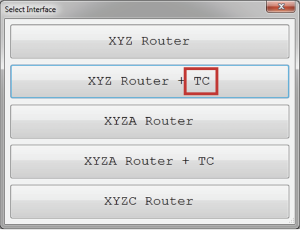
Figure (23)
After installing the interface and opening the Radonics software, the necessary settings for using the Tool Changer must be applied. To do this, first, the Settings window should be opened and the ToolChanger branch, where all the settings related to the Tool Changer exist, should be accessed. In this section, we will explain the essential settings for setting up the Tool Changer.
- Note that in the table related to the ToolChanger section (Table 18) and also in the tables related to different types of links, all settings and features related to automatic tool changing in the controller are fully explained, and the user can use other Tool Changer features according to their needs.
In the next step, based on the variety of tool changing methods (which are determined based on the type of tool parking on the machine), there are different tool changing options in the Radonics software that the user should choose according to the tool changing method available on their machine. To do this, go to the ToolChanger branch and the Type variable to determine the type of tool changer on the machine (for more information on the types of tool changing methods, please refer to table number 18 in the ToolChanger branch).
After determining the type of tool changer, we need to set the necessary digital inputs and outputs to issue the essential commands for tool changing. To do this, first go to the System branch and the InPorts sub-branch, and select the desired input. Now, by opening one of the desired inputs, you will encounter three variables for the settings on each of the inputs, which are Enabled, Link, and NC, respectively (for more information on how each of the 3 digital input variables works, please refer to the table in the System branch under the InPorts sub-branch). To perform the tool changing operation, you need 5 inputs, and you should set the links T-ToolHolder,1 (Function link in Table 4), and T-ToolHeightSensorPin (Input link in Table 2), T-HSD-S1Pin or (T-ToolSensorPin, T-TEKNO-S2Pin, T-CC-S1Pin) (Input link in Table 2), T-HSD-S2Pin or (T-CC-S2Pin, T-TEKNO-S1Pin, T-ToolHolderSensorPin) (Input link in Table 2), and T-HSD-S3Pin or (T-CC-S3Pin, T-TEKNO-S3Pin, T-SpindleRotationSensorPin, T-InverterStopPin) (Input link in Table 2) for them (for more information, please refer to Tables 2 and 4). After that, go to the System branch and the OutPorts sub-branch and select the desired output. Now, by opening one of the desired outputs, you will encounter three variables for setting each of the outputs, which are Enabled, Link, and NC, respectively (for more information on how each of the digital output variables works, please refer to the table in the System branch under the OutPorts sub-branch). To perform the tool changing operation, you need 2 outputs, and you should define the links T-ToolHolderPin and T-ToolCleanerPin for them (for more information, please refer to Table 3).
- Note that the initial settings for setting up the tool changer in the input and output sections have been done by default.
After setting up the inputs and outputs, go back to the ToolChanger branch and adjust the remaining essential variables for the tool changing process. (For more information, refer to the ToolChanger table (Table 18) in the ToolChanger branch.)
After setting the ToolChanger variables, the coordinates of all the tool parking locations must be determined under the Tools sub-branch in the ToolChanger branch. To do this, first home the machine and then place each tool with its ISO in the desired parking number.
- ISO is one of the taper standards widely used in router machines in various sizes such as ISO30, ISO40, and ISO50 according to the specific requirements.
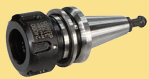
Now, by manually moving or jogging the spindle, it is moved to the position of each tool in the parking area. At this stage, it must be ensured that the gripper is open when the ISO is placed on the spindle (the gripper being open depends on the output that was previously set using the T-ToolHolderPin link (output link in table 3)). A momentary switch connected to the T-ToolHolder,1 digital input link can be used to issue the command, or a virtual button can be added to the software with the same T-ToolHolder,1 link to toggle the output. Now, with great precision, the spindle is brought up to the top of each tool so that the ISO, along with the tool, is fully seated in the tool holder clamps. After that, on the main screen of the software, the Absolute coordinate values of each axis, which indicate the position relative to the home point, are entered separately for the coordinates of each parking space, and all parking spaces must be defined in the same way (Figure 24).
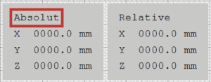
Figure (24)
In the final step, the tool height measurement, which is one of the most essential steps in the tool changing process, is performed. In this step, first make sure that the input with the T-ToolHeightSensorPin link (input link in table 2) is defined, and then enter the tool height sensor coordinates in the ToolChanger branch and ToolHeightSensor sub-branch in order of axes (for more information, please refer to the ToolChanger table (table number 18) in the ToolChanger branch).
- Please note that in general applications, we set the ToolReference value to zero. In cases where automatic tool height measurement is not performed and the user wants to measure the tool height using a caliper, the ToolReference value should be set equal to the spindle collet offset value relative to the Z-axis zero point.
- Please note that tool height measurement should be performed after defining the parking positions.
Introduction to the Interface Editing Environment
In this section, we will provide a comprehensive explanation of the interface editing page and all its elements. By simultaneously pressing the CTRL+SHIFT+ALT+Home shortcut key, the interface editing environment opens, which provides the user with the ability to customize and make visual changes to the interface. In fact, users can add or remove different elements in the interface according to their needs, as well as determine or change parameters and links of the elements. (Figure 25)
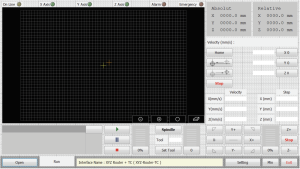
Figure (25)
Making Changes to Elements
Right-clicking on any of the elements on the page opens a window where changes can be made to the selected element using the available parameters. Additionally, the style of the element can be copied, pasted, or deleted in this window. (Figure 26)
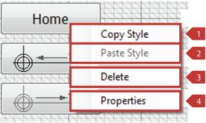
- Note that the numbers in the table below are based on the numbering of elements in Figure 26.
|
Name of the Element |
Descriptions |
|
|
1 |
Copy Style |
In order to copy all the specifications related to the desired element, including size and the settings in the Properties section (please refer to row number 4 in this table), use the Copy Style item. Note that after copying the specifications related to the desired element, you can transfer the specifications to another element of the same type using the Paste Style item. For example, if the specifications related to a Button element have been copied, you can only transfer those specifications to another element of the same type (i.e. another Button). |
|
2 |
Past Style |
To transfer all the specifications related to the desired element, including size and the settings in the Properties section (please refer to row number 4 in this table) that have been copied using Copy Style, use the Paste Style item. Note that after copying the specifications related to the desired element, you can transfer the specifications to another element of the same type using the Paste Style item. For example, if the specifications related to a Button element have been copied, you can only transfer those specifications to another element of the same type (i.e. another Button). |
|
3 |
Delete |
Clears the desired element entirely. |
|
4 |
Properties |
By pressing the Properties item, a window opens that allows you to view or change the variables related to the desired element. Note that the number and types of variables in the window are different depending on the type of element. For example, the Properties window for a Button element is shown in the following figure:
All the variables in the Properties window are explained separately in table number 21. |
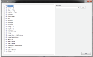
Table (19)
Adding an Element
By right-clicking on the interface editing environment, a window shown in figure 27 will open at points where no element exists.
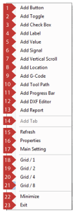
Figure (27)
|
Name of the Element |
Descriptions |
|
|
1 |
Add Button |
The appearance of the Button element on the interface editing page: By right-clicking on the existing Button element on the page and then pressing the Properties item, a window opens where you can adjust the variables related to the Button element. All the variables available in the Properties window are explained in table number 21. Note that since the Link variable in the Properties window is different for each element, the table for it is written separately for each element. |
|
2 |
Add Toggle |
It is used for 2-state commands. In fact, by pressing the Toggle, the corresponding link is turned on if it is off, and turned off if it is already on. For example, the Toggle key is used to turn the spindle on and off. The appearance of the Toggle element on the interface editing page: By right-clicking on the existing Toggle element on the page and then pressing the Properties item, a window opens where you can adjust the variables related to the Toggle element. All the variables available in the Properties window are explained in table number 21. Note that since the Link variable in the Properties window is different for each element, the table for it is written separately for each element. |
|
3 |
Add Check Box |
It is used for 2-state commands. In fact, when the Check Box is checked, the output is turned on, and when it is unchecked, the output is turned off. For example, the Check Box can be used to turn vacuum on and off. The appearance of the Check Box element on the interface editing page: By right-clicking on the existing Check Box element on the page and then pressing the Properties item, a window opens where you can adjust the variables related to the Check Box element. All the variables available in the Properties window are explained in table number 21. Note that since the Link variable in the Properties window is different for each element, the table for it is written separately for each element. |
|
4 |
Add Lable |
The Label element is used to display text, title, or the desired variable value to the user. For example, the speed of the machine can be displayed using this element. Note that this element only allows you to view the desired variable or entered text, and it does not have the ability to edit or change the variable using this element. The appearance of the Label element on the interface editing page: By right-clicking on the existing Label element on the page and then pressing the Properties item, a window opens where you can adjust the variables related to the Label element. All the variables available in the Properties window are explained in table number 21. Note that since the Link variable in the Properties window is different for each element, the table for it is written separately for each element. |
|
5 |
Add Value |
The Value element is used to view and modify variables. The Value element can be used to both view and modify a variable. To access the Properties window and adjust the variables related to the Value element, right-click on the Value element on the interface editing page. All of the available variables in the Properties window are explained in Table 21. Please note that the Link variable in the Properties window is different for each element, so the table is written separately for each element.. |
|
6 |
Add Signal |
The Signal element is used to display variables that include two states of True and False. This element comes in three different colors. View of the Signal element in the interface editor: By right-clicking on the Signal element that exists on the page and then pressing the Properties item, a window opens in which the variables related to the Signal element can be adjusted. All the variables available in the Properties window are explained in table number 21. Note that, since the Link variable in the Properties window is different for each of the elements, the table is written separately for each element. |
|
7 |
Add Vertical Scroll |
It is used to change some variables. For example, Scroll has been used for Feed variables. Appearance of Vertical Scroll element on the editing page of the interface: When right-clicking on the Vertical Scroll element on the page and selecting the Properties item, a window opens in which you can adjust the variables related to the Vertical Scroll element. All the variables available in the Properties window are explained in Table 21. Please note that since the Link variable in the Properties window is different for each element, the table is written separately for each element. |
|
8 |
Add Location |
It is used to display the axis coordinates in either Absolute or Relative form: Absolute displays the axis coordinates relative to the Home. Relative displays the axis coordinates relative to the Reference. Appearance of Location element on the editing page of the interface: When right-clicking on the Location element on the page and selecting the Properties item, a window opens in which you can adjust the variables related to the Location element. All the variables available in the Properties window are explained in Table 21. |
|
9 |
Add G-Code |
After loading the desired file using the Open element, in this section, G-Code and program lines are displayed. Additionally, during program execution, the executed parts are identified with a different color. Appearance of G-Code element on the editing page of the interface: When right-clicking on the G-Code element on the page and selecting the Properties item, a window opens in which you can adjust the variables related to the G-Code element. All the variables available in the Properties window are explained in Table 21. |
|
10 |
Add Tool Path |
The loaded file is displayed in this section, and you can observe the machine’s operation and the order of program code execution, both in simulation and during operation. Additionally: In the upper-left part of this section, the address of the file that the user has loaded and the Work Size, which displays the dimensions in different axes, and the Work Length, which displays the total length of the workpiece, are visible. In the lower-right part of this section, you can view the file from different perspectives and zoom in or out on the design. Holding down the right mouse button allows you to view the design from different angles. Appearance of Tool Path element on the editing page of the interface: When right-clicking on the Tool Path element on the page and selecting the Properties item, a window opens in which you can adjust the variables related to the Tool Path element. All the variables available in the Properties window are explained in Table 21. |
|
11 |
Add Progress Bar |
It is used to display information such as: In normal mode, it displays the interface name. During operation, it displays the estimated time and the remaining time for the operation. In case of any alarm or emergency, this section changes to red and displays the created alarm. Double-clicking opens the Debug Form window, where you can view the performance report of the controller and software, the Radonics software version, the interface type, and alarms. Pressing the CTRL+SHIFT+ALT+PrtSc shortcut key opens the device performance report in Notepad. Appearance of Progress Bar element on the editing page of the interface: When right-clicking on the Progress Bar element on the page and selecting the Properties item, a window opens in which you can adjust the variables related to the Progress Bar element. All the variables available in the Properties window are explained in Table 21. |
|
12 |
Add Tab |
It is used to add a new section or Tab. Please note that this element is not active in all parts of the editing page of the interface and can only be viewed by right-clicking on the lower toolbar of the editing page of the interface. (The active range of this element is shown in the figure below.) When right-clicking, a new Tab is created, as shown in the figure below. Pressing Add Tab adds a new Tab to the interface. Appearance of Tab element on the editing page of the interface: When right-clicking on the Tab element on the page and selecting the Properties item, a window opens in which you can adjust the variables related to the Tab element. All the variables available in the Properties window are explained in Table 21. |
|
13 |
Refresh |
Refresh or Reload is a common term used to update or reload the displayed or saved content. For example, if a user changes the size of the Location element but the variables in this element do not change, then Refresh is used in this case. |
|
14 |
Properties |
By clicking on the Properties item, a window is opened to view and apply changes to the variables related to the desired element. |
|
15 |
Main Setting |
Initially, by clicking on the Main Setting item, the Setting window with two different tabs, Setting and Security, is opened. In the Setting section, all the main settings of the Radonix software are included, and in the Security section, all the settings related to activation code and time locks are included, as well as the Export button to get a backup file of the applied settings up to that moment. In this page, there are also links to the Radonix Telegram channel and website, which by clicking on them, you can easily enter the official Telegram channel and website of the Radonix company. |
|
16 |
Grid / 1 |
Elements can be moved within the rectangles specified in the figure below. As the rectangle is not divided into smaller units, the movement is carried out with a low precision. |
|
17 |
Grid / 2 |
Elements can be moved within the rectangles defined in the image below. In this case, since the rectangle is divided by 2, the movement is done with a precision of 2 times the Grid/1. |
|
18 |
Grid / 4 |
Elements can be moved within the rectangles defined in the figure below. Since the rectangle is divided by 4, movement is done with a precision of 4 times the Grid/1. |
|
19 |
Grid / 8 |
Elements can be moved within the rectangles specified in the figure below. Since the rectangle is divided by 8, movement is done with an accuracy of 8 times Grid / 1. |
|
20 |
Minimize |
It is used to minimize or reduce the size of the interface editing window. |
|
21 |
Exit |
It is used to exit the interface editing window. |
Table (20)
In the table below, all variables available in Properties are fully explained.
|
Name of the Element |
Descriptions |
|
|
1 |
% |
Password A variable used to store the password for the Tab element. |
|
2 |
Align |
Display Mode Location Used to specify the location of the toolpath display status buttons. |
|
3 |
Axes |
Displayed Axes Displays the axes used in that element. |
|
4 |
BackColor |
Background Color Used to determine the background color of the interface, tab, or element. |
|
5 |
BackColor2 |
Secondary Background Color Used to determine the background color of elements that have a secondary background. |
|
6 |
BackgroundImage |
This variable is used to set the background image of a tab. |
|
7 |
BackgroundImageLayout |
This variable can be set to 5 different modes, including: |
|
8 |
BarColor |
This variable is used to determine the color of the Progress Bar. |
|
9 |
Border |
This variable is used to determine the thickness of the border of some elements. |
|
10 |
BorderColor |
The color of the border is determined by this variable. |
|
11 |
Click |
The Click variable is defined as True or False. Using this variable, the type of mouse behavior in the desired element can be determined. If this variable is False, holding and releasing the desired element will have an independent conceptual meaning. For example, in situations where the Button element is used for manual movement and the value of this variable is set to False, pressing the Button will start the movement and releasing it will stop it. If this variable is True, holding and releasing the desired element will not have an independent conceptual meaning, and only the link command of that element will be executed. |
|
12 |
DoneColor |
It is used to determine the color of the executed parts of the program in GCode and Toolpath elements. |
|
13 |
Enabled |
The Enabled variable is defined as True or False. If this variable is False or undefined, the tab or element will be disabled and ignored. If this parameter is True, the desired tab or element will be enabled. |
|
14 |
ErrorColor |
This variable is used to determine the color of error sections in GCode and Toolpath elements. |
|
15 |
FitImage |
This variable is used to determine the type of image alignment on a tab or element and can be defined in three different modes: |
|
16 |
Flat |
This variable is used to flatten (show non-raised) a button. |
|
17 |
FlatBorder |
To create a border around a button that has been set to Flat or non-raised mode, this variable is used. |
|
18 |
FlatDesignBorder |
When a 3D file is added to Toolpath: If this variable is False, only a rectangle will be created on the design floor. If this variable is True, a cube, the envelope, will be created on the design. |
|
19 |
Font |
The font used in the interface, tab, and element is determined by this variable. The user is only allowed to use the names of installed fonts on the operating system, otherwise it may cause errors in the program. |
|
20 |
Font2 |
This variable is used to determine the font used in elements that have secondary fonts. The user is only allowed to use the names of installed fonts on the operating system, otherwise it may cause errors in the program. |
|
21 |
FontSize |
This variable is used to determine the font size in the interface, tab, and element. The font measurement unit is points. |
|
22 |
FontSize2 |
This variable is used to determine the font size used in elements that have secondary fonts. The font measurement unit is points. |
|
23 |
FontStyle |
The font mode of the interface, tab, and element can be set by this variable. It can be defined in the following modes: |
|
24 |
FontStyle2 |
In elements that have secondary fonts, the font mode of the interface, tab, and element can be set by this variable. It can be defined in the following modes:
|
||||||||||||
|
25 |
ForeColor |
This variable is used to determine the color attribute of the text in the interface, tab, or element. |
||||||||||||
|
26 |
ForeColor2 |
This variable is used to determine the color attribute of the text in the interface, tab, or element for elements that have secondary fonts. |
||||||||||||
|
27 |
Format |
This variable can be used to determine how numbers are displayed in some elements. Standard string formats for this purpose are used in this variable in programming. For example, some cases are: 0 displays integer number. 00 displays integer number with at least two digits (e.g. 5 is displayed as 05). 0.000 displays decimal number with three significant digits and at least three trailing zeros after the decimal point. 0.0## displays decimal number with three significant digits and at least one zero after the decimal point. 0% displays integer number as a percentage.
|
||||||||||||
|
28 |
FrameColor |
The color of the frame drawn around an element is determined by this variable. |
||||||||||||
|
29 |
Grid |
In the Toolpath display element, the distance between guide lines along the axes is determined by this variable. The unit of this variable is equal to the unit set in calibration. |
||||||||||||
|
30 |
GridColor |
In the Toolpath display element, the color of guide lines along the axes is determined by this variable. |
||||||||||||
|
31 |
Group |
It is used for grouping elements. Note that this variable must be the same for all elements within a group. Groups are displayed using toggle keys. The function of groups is the same as tabs. |
||||||||||||
|
32 |
Height |
It determines the number of rows on the interface display and the height of elements. With this variable, the user can divide the display into a desired number of rows, and the number of rows remains fixed on different computer monitors by adjusting the dimensions of the display. In elements, this variable is used to determine the height of elements in terms of row dimensions. For example, if we consider the number 1 as the height of the element, the actual height of the element in pixels is almost equal to the height of the monitor in pixels divided by the number of rows defined on the interface display. The value of this variable should not exceed one less than the number of rows defined on the interface display. |
||||||||||||
|
33 |
HighlightColor |
In Toolpath, the color of the status setting keys can be specified. In the Toggle button, the color of the Toggle button text can be specified in the On state. |
||||||||||||
|
34 |
HighlightImage |
The image of the Toggle button in the On state can be specified. |
||||||||||||
|
35 |
HighlightText |
The text of the Toggle button in the On state can be specified. |
||||||||||||
|
36 |
Image |
The desired image can be specified in the element. |
||||||||||||
|
37 |
ImageAlign |
The display mode of the image in the elements can be determined. |
||||||||||||
|
38 |
ImageTextRelation |
If this variable is False, and there is both an image and text in the element, they are displayed side by side. If this variable is True, and there is both an image and text in the element, they are displayed on top of each other. |
||||||||||||
|
39 |
Left |
The position of the element on the interface display in terms of column dimensions is determined by this variable. The value of this variable should not exceed one less than the number of columns defined on the interface display. |
||||||||||||
|
40 |
LineFactor |
In GCode, the display distance between lines can be changed using this variable. For example, the number 0.5 is half the distance between lines in normal mode. |
||||||||||||
|
41 |
Link |
The link between elements and functions, parameters, inputs and outputs, etc. is determined by this variable. The Link for each element is described in Table 20 of the element descriptions. |
||||||||||||
|
42 |
PointerColor |
The color of the position indicator in the Toolpath element is determined by this variable. |
||||||||||||
|
43 |
Precision |
This variable determines the number of significant decimal places displayed in the parameter display. |
||||||||||||
|
44 |
ReferenceColor |
The color of the reference position indicator in the Toolpath element is determined by this variable. |
||||||||||||
|
45 |
Relative |
If this variable is False, the Location element displays the axis coordinates in Absolute format. If this variable is True, the Location element displays the axis coordinates in Relative format. |
||||||||||||
|
46 |
Step |
When using the Keypad, the value of the Step variable in the Value element is determined by the and keys for decreasing ( ) or increasing ( ) the values. |
|
47 |
ShowTime |
Displays the duration of the status adjustment keys being active in the Toolpath element. |
||||||||||
|
48 |
SignalColor |
This variable can be used to determine the color of the Signal element. This variable has three colors: red, green, and yellow. |
||||||||||
|
49 |
TableColor |
This variable can be used to determine the color of the cube displayed on the environment design. |
||||||||||
|
50 |
Text |
This variable determines the displayed text in the elements. |
||||||||||
|
51 |
TextAlign |
This variable determines the position of the displayed text. |
||||||||||
|
52 |
TextFormat |
This variable can be used to determine how text is displayed in some elements. Standard string formats used in programming are used in this variable. For example:
|
||||||||||
|
53 |
Top |
The position of elements on the interface screen is determined by this variable in terms of row dimensions. The value of this variable should not exceed the number of rows defined in the interface minus one. |
||||||||||
|
54 |
TransparentEnabled |
If this variable is False, transparent colors are not used in the Toolpath element. If this variable is True, transparent colors can be used in the Toolpath element. |
||||||||||
|
55 |
TraveseColor |
This variable is used to determine the color of the displacement (G0) in the GCode and Toolpath elements. |
||||||||||
|
56 |
Type |
This variable is used to determine the type of element, which can be defined in the following modes: {Button, Toggle, Value, Label, Signal, GCode, Location, Scroll, ToolPath}. |
||||||||||
|
57 |
Width |
The number of columns on the interface screen and the width of the element are determined by this variable. Using this variable, the user can divide the interface screen into a desired number of columns, and with changing the screen dimensions on different computers, this number of columns remains constant, and the interface adjusts the screen by dragging the elements. This variable is used to determine the width of the element in terms of column dimensions. For example, if we consider the number 1 as the width of the element, the actual width of the element in pixels is approximately equal to the monitor width in pixels divided by the number of columns defined in the interface screen. The value of this variable should not exceed the number of columns defined in the interface. |
||||||||||
|
58 |
WorkColor |
This variable is used to determine the color of the cutting lines (G1) in the GCode and Toolpath elements. |
Table (21)
Introduction to Visual Effects
In this section, we will provide a comprehensive explanation of Visual Effects and its capabilities. Initially, by pressing the Ctrl+Shift+Alt+F5 shortcut keys simultaneously, the Visual Effects window can be opened. This window enables the user to activate Visual Effects in the current interface and select a new theme. Using these themes, the user can change the overall appearance of the program and also create a new interface with a custom name and caption while preserving the previous interface. Additionally, the display method of elements within the page can be modified. For example, the border color, corner rounding of elements, color gradient, and the presence or absence of a light in Toggle elements can be changed. (Figure 28)
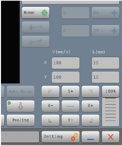
Figure (28)
After pressing the shortcut key Ctrl+Shift+Alt+F5 simultaneously, the Interface Utility window (Figure(29)) opens.
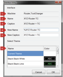
Figure (28)
|
Descriptions |
|
|
1 |
This displays the type of interface (device type). |
|
2 |
This is the current name of the interface. It is the name with which the interface has been saved. |
|
3 |
This is the current caption of the interface. It is visible on the interface selection page in case there are multiple interfaces. |
|
4 |
The new name for the interface is defined in this section. |
|
5 |
The new caption for the interface is defined in this section. |
|
6 |
A list of pre-defined themes is provided in this section. If you do not want to change the interface theme, select Current Theme. |
Table (22)