
As explained in detail in Chapter 2 regarding the wiring and voltage supply of the controller, turn on the controller and make sure the Power LED lights up. Then, connect one side of the LAN cable to the LAN port of the controller and the other side to the computer. To establish the connection between the controller and the computer, perform the following basic settings in order. Note that these settings only need to be done once and are saved after the controller and computer are connected.
IP definition
⚠️ To set the IP, after connecting the controller to the computer, open the “Not Pro” program.
To set the IP, follow these steps in order:
1. Go to the Start menu in Windows.
2. Go tothe Control Panel
3. Follow the steps shown in Figures 28 to 35 in order.
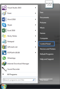
Figure (28)
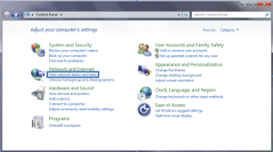
Figure (29)
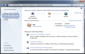
Figure (30)
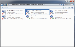
Figure (31)
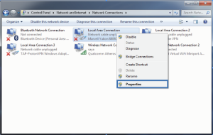
Figure (32)
⚠️ According to step 6, first click on Internet Protocol Version 4 (TCP/IPv4) to make it blue, then according to step 7, click on Properties. (Figure 33)
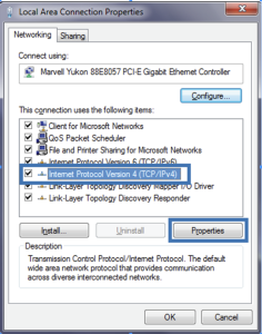
Figure (33)
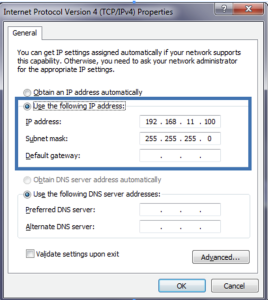
⚠️ According to step 8, select “Use the following IP address”. Then, enter the IP address used in the controller, which is 192.168.11.100, and the Subnet mask, which is 255.255.255.0. Finally, click OK (refer to Figure 34). Close any remaining open windows.
Figure (34)
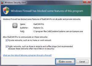
⚠️ After setting the IP, a warning may appear from the Windows Firewall after running each of the Cam Pro programs (Cam Pro, Cam Pro Test, and Cam Pro Calibrator), indicating that the connection is being blocked. In this window, you are asked to allow communication through the network port. To do so, follow the steps in 9 and 10, tick the two options, and finally click the “Allow Access” button. This will allow Windows to communicate with the Cam Pro programs through the network port. (Refer to Figure 35)
Figure (35)
⚠️ If you did not correctly perform steps 9, 10, and 11, and the IP is blocked by the firewall or if an antivirus is installed on the computer and is blocking the connection between the controller and the computer, then follow the steps shown in Figures 36 to 45 in order to resolve the issue.
Figure (36)
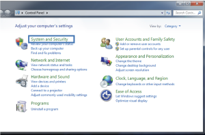 Figure (37)
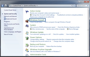 Figure (38)
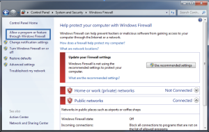 Figure (39)
⚠️ If the software appears in gray color in the “Allow a program or feature through Windows Firewall” environment, you will not be able to make changes. To be able to make changes, click on “Change settings” as shown in Figure 40. If the software appears in black color, this means you have the ability to make changes, so you can skip this step and do not need to follow step 5. (Refer to Figure 40)
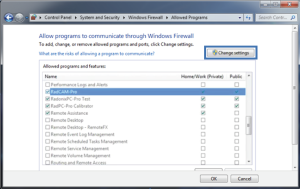
Figure (40)
⚠️If the Radonix software (RadCAM-Pro, RadonixPC-Pro Test, RadPC-Pro Calibrator) is not listed in the “Allow a program or feature through Windows Firewall” environment (refer to Figure 41), you need to follow steps 6 to 8 as shown in figures 41 to 43. However, if the software is already listed, you can skip these steps and do not need to perform steps 6 to 8.
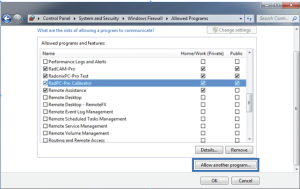
Figure (41)
⚠️ In step 7, you should find Radonix files from the Browser section and add them to the list. (Figure 42)
Figure (42)
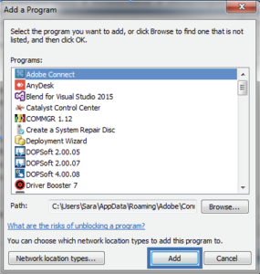
Figure (43)
⚠️ According to step 9, all squares within the box should be checked (ticked) and if a checkmark is missing, it should be added by clicking within the check box. (Refer to Figure 44 for visual reference).
Figure (44)
Now you are able to launch the Radonix software.
⚠️ If the CNC controller and computer are properly connected and the necessary power supply voltage is being supplied to the controller, the LAN connector LEDs on the controller should be either blinking or on. If these LEDs are off, it can be concluded that the cable connection between the controller and the computer is disconnected or there is an issue with the connector.