In CNC router machines and all other CNC machines, it is necessary for the machine to have knowledge of all the points within the limited machining space so that the movement of the tool on the workpiece can be defined in terms of known coordinates. This is achieved by having control axes embedded in the machine that control movement in linear paths and/or rotations. These axes include the main axes, auxiliary axes, and rotary axes, which control the direction of movement of the table or tool.
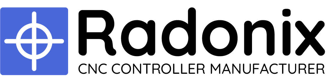
The primary axes are typically designated as X, Y, and Z, and they must be perpendicular to each other. The auxiliary axes, which are aligned with the primary X, Y, and Z axes, are named U, V, and W. These axes are not considered independent axes and are used to supplement the limited movement of the primary axes. In addition to these axes, there is also a rotary axis that is built around the X, Y, and Z axes, and it is designated as A, B, and C, respectively. (Figure 1)
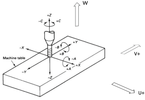
Figure (1)
How to determine coordinate axes
The way to determine the direction of the axes of the device is based on the right-hand rule that if we hold the three middle, index, and thumb fingers together perpendicularly, the middle finger is the Z+ axis, the index finger is the Y+ axis, and the thumb is the X+ axis. Obviously, the negative directions of X, Y, and Z are opposite to the direction shown. It should be noted that the Z axis is always aligned with the rotary axis, and the positive direction of Z is from the workpiece to the tool.
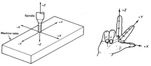
Figure (2)
To determine the direction of the rotation axes A, B, C, we hold the right hand so that the thumb points in the positive direction of the X, Y, Z axes. The direction of rotation indicated by the other four fingers, when they are closed, shows the positive direction of the A, B, C axes. It is important to note that the negative directions of A, B, C are opposite to the direction indicated by the fingers.
Figure (3)
Types of interface
Different interfaces have been developed based on the coordinates used in the router. As explained in the previous section, which discussed the types of coordinate axes, it is easy to understand the interfaces and their usage. You can reach out to the interfaces via QR provided in Figure(5) from Radonix Github
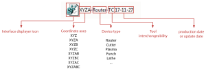
Figure (4)
- If TC is written, it has tool interchangeability.
- If TC is not written, it does not have tool interchangeability.
or you can click here for download directly

Figure(5) – Interfaces download link