CAM-Pro Test software is installed along with CAM-Pro software and there are two ways to find it after installation. According to the first method, simply go to the location of the software installation, which is by default in the C drive of Windows, and then go to the (x86) Program Files folder and open the Radonix folder. The CAM-ProTest software can be found in the Radonix CAM-Pro file. According to the second method, simply search for the Radonix CAM-Pro Test software in the Start menu search bar (step 2 in figure 1) and then run it. (Figure 1)
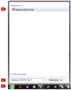
Figure (1)
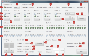
When running the CAM-Pro Test software, you will be faced with Figure (2), which includes groups of Connection, Activation, Axes, InPort, OutPort, Analog, Clock, Remote, and Handwheel, each of which contains various components. In Table (1), we provide separate definitions for all of these components.
⚠️ Note that you should never run two Radonix software at the same time, as this will cause one of the software to not go online. Therefore, be sure to close the other Radonix software when running the desired software.
Figure (2)
ch
Activation
1
It displays the connection between the controller and the computer. If the connection between the controller and the computer is established correctly and the IP is set correctly (please refer to Chapter 3.3.1, section “Defining IP” for IP configuration), the light turns on.
2
It is used to select the type of connection between the controller and the computer (USB/LAN). In Pro USB controllers, it must be set to USB mode, and in PC-Pro LAN and PC-Smart controllers, “LAN” must be selected.
Activation
3
The controller serial number is displayed in this section after the controller goes online.
4
This is the place to enter the activation code or 16-digit code. By entering the activation code, the required axes will be activated based on the type of code and the type of purchased controller. After entering and confirming the activation code by pressing the Enter button, the axes will change from gray and off state to colorful and on state.
5
Displays the number of activated axes.
6
Displays the purchased option code.
Axis
7
By clicking on the box, the corresponding axis will be activated (the motor related to that axis will turn on).
8
This displays the feedback “Ready” for the axes. If the wiring between the controller and drivers is correct, and the axis is activated by clicking on the S-ON box (which stands for Servo ON), the RDY box (which stands for Ready) will turn on. The on state of the RDY box indicates the normal state of the corresponding axis. Note that the Radonix board also has LEDs for Servo ON and Ready, and the same thing happens to those LEDs as well.
9
This option is used to change the axis movement.
10
This displays the pulse rate for the axis, which has a direct relationship with the speed of the axis movement.
11
This is used to move the motor in the negative direction of the corresponding axis. In other words, if the corresponding axis is active and its RDY light is on, clicking and holding on the – box will cause the motor to turn clockwise or counterclockwise. Note that if the axis moves in the positive direction due to wiring or driver logic, the movement direction can be changed using section 9 of this table.
12
This is used to move the motor in the positive direction of the corresponding axis. In other words, if the corresponding axis is active and its RDY light is on, clicking and holding on the + box will cause the motor to turn clockwise or counterclockwise. Note that if the axis moves in the negative direction due to wiring or driver logic, the movement direction can be changed using section 9 of this table.
Please note that if the motor rotates in one direction by pressing both + and – buttons, there may be a mistake in the wiring.
13
This is used to change the pulse speed in percentage. In other words, motor speed can be changed in percentage using this element.
14
If any of the motors have an alarm and the corresponding axis is disabled, this element is used to execute a reset command to clear the motor alarms.
Please refer to Chapter 3, section 3.2.6 (Axes) for more information.
InPort
15
This displays the status of the digital inputs on the Radonix controller, and if any of the inputs are turned on, the corresponding LED in the software will also turn on. For example, if input number 2 on the controller is turned on, LED 02 will turn on in the software. Please refer to Chapter 2, Section 2.2.3 (Digital Inputs) for a complete understanding of the inputs’ operation and the concepts of NPN and PNP.
OutPort
16
The toggle buttons are used to turn the digital outputs on and off on the Radonics controller, and by clicking on each of the squares in the Out Port section, the corresponding LED for that output should turn on on the Radonics board. For example, if you click on the square for output number 02, the LED number 00.02 on the controller should turn on. Please refer to Chapter 2.2.4 (Digital Outputs) for a complete understanding of the output functions.
Analog
17
This is used to test analog output 1 and PWM1.
18
This is used to test analog output 2 and PWM2.
These scroll bars range from 0 to 100 and correspond to variable voltage output. The number 0 corresponds to 0 volts and the number 100 corresponds to 10 volts. To ensure the health of the analog outputs, it is sufficient to measure the analog voltage with a multimeter. The black probe should be placed on GND and the red probe should be placed on AO1 or AO2. Now by moving the scroll bar, the displayed voltage on the multimeter should change in the same proportion. Additionally, to test the health of the PWM outputs on the board, the PWM voltage value can also be viewed. Note that the PWM voltage value is always half of the AO voltage value. For example, if AO1 is 10 volts, PWM1 is 5 volts. For a complete understanding of the analog and PWM output function, please refer to section 3.2.5 (Analog and PWM Outputs) of chapter 3.
Clock
This section is designed to test the functionality of the embedded controller clock, and to activate this section, the T-Code must be entered in the Activation group and in the rectangle where the 16-digit Activation Code is entered. By entering the T-Code, this section will be activated and will change from the off and gray state to the on and colorful state, and the Update option will also be activated.
T-Code stands for Time Keeper Code, which is a 16-digit code similar to A-Code that is responsible for activating the controller clock and the settings related to the time lock.
19
After verifying the entered T-Code, the status of the controller’s internal clock can be viewed from this section. (OK/Error) If the internal clock is healthy and the T-Code is correct, OK will be displayed.
20
It is used to display the controller’s internal clock. If the Update button is pressed, the displayed time is synchronized with the computer’s clock, and the internal clock of the controller can be adjusted in this way.
21
It is used to display the device’s operating time.
22
It is used to display the controller’s internal date.
23
It is used to display the date of the controller’s update.
24
It is used to display the controller’s tag.
25
The command button for updating the internal clock of the controller.
Note that in order to update the controller’s date, the computer’s clock must be up to date. Otherwise, the time locks will not work properly.
Remote
Please note that in order for this section to be activated, the CDM21XXX driver must be installed. If this driver is not installed, the remote section in CAM-Pro Test software will be grayed out and offline. For instructions on installing the CDM21XXX software, please refer to Chapter 5, section 5.2.2.6.7 (Remote).
Please refer to Chapter 5, section 5.2.2.6.7 (Remote) for a complete understanding of the remote functionality before proceeding with the explanations in this section.
26
This section is used to display the status of the remote (Online/Offline).
27
This section is used to display the number of the button pressed on the remote transmitter, which is used to test the remote. In fact, if the remote serial number and channel are entered correctly, pressing any button on the remote transmitter will display a number corresponding to that button in front of the Key.
28
The serial number of the remote transmitter must be entered in this section. The serial number of the remote transmitter is a 5-digit number that is printed on the back of the remote case and must be entered in the rectangle in front of Serial, and then the Enter button must be pressed.
29
The Automatic Scan command is used to automatically scan the remote, which allows you to find the channel number by holding down one of the transmitter buttons.
30
The frequency channel number of the remote transmitter is entered in this section. If the user is not aware of their remote channel number, the method of changing the remote transmitter channel is described in chapter 4, section 4.2.2.6.7 (Remote), and the corresponding table is provided. Please refer to that section.
Handwheel
31
This is used for counting Hall sensor pulses. Please refer to Chapter 2, section 2.2.7 (Hall sensor and RS-485) for information on the structure of the Hall sensor terminal on the Radonix board and how it operates.
OutPort Fault
32
As the outputs are protected against short circuits and high current-induced heat, in case of any of these occurrences, an error will be displayed by the red LED labeled O-Error on the board. In case of an error, all outputs will be deactivated by the controller. Also, a red OutPort Fault light is embedded on the software, which lights up in case of such errors.
Exit
33
By pressing this button, the CAM-Pro Test software will be closed.
Table (1)